
User`s guide


M3000A/M3046AM3015A/M3016A Service Guide
1-38 Introduction to the Instrument
Each temperature value consists of 16 averaged samples and the test resistor verifies the
linearity of the measurement. With an offset resistor all offsets are eliminated.
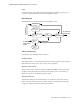
3UHVVXUH7HPSHUDWXUH0RGH'HWHFWRU
The CPU switches between two different A/D converter controls and wave processing
algorithms depending on the connected transducer: Pressure or Temperature. To recognize
the presence of a pressure transducer, a coding within the transducer is checked. To recognize
the presence of a temperature transducer, the transducer’s resistance is measured and must be
within specified limits. This is only done when no pressure transducer is present.
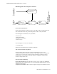
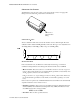
%ORFNGLDJUDPRIWKH7HPSHUDWXUH6RIWZDUH0RGXOH
6LJQDO$FTXLVLWLRQ
This module is responsible for the A/D conversion of the analog signal from the temperature
transducer. The Signal Acquisition module provides a raw temperature value to the Average
Calculation module. The module also performs various self-tests and consistency checks to
ensure proper operation and reports errors and failures to the Alarming Module.
$YHUDJH&DOFXODWLRQ
This component averages the raw measured temperature values over an interval of 1 second.
The averaged values are converted to the user-selected unit.
7HPSHUDWXUH$ODUPLQJ
This component generates high/low alarms if an alarm limit is exceeded. Additionally, a
technical alarm is generated if no temperature can be measured.
7HPSHUDWXUH8VHU&RQWUROV
This component controls the user-selected settings:
• Set temperature alarm limits
• Select the temperature measurement units
7R)URP,QYDVLYH3UHVVXUH
Average
Calculation
Temperature
Alarming
Temperature
Controls
Pressure Waveform
Temp. Value
Temp. User Controls
Temp. Alarms
7HPSHUDWXUHVRIWZDUH