
User`s guide


M3000A/M3046A/M3015A/M3016A Service Guide
Introduction to the Instrument 1-35
6DIHW\
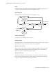
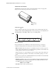
To ensure the safety of the patient, the patient-applied part is isolated from ground by opto-
couplers and a transformer. The circuit is also encapsulated in plastic.
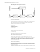
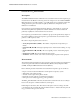
%ORFN'LDJUDP
This illustration shows the block diagram of the Temp/Press circuit.
7KHRU\RI2SHUDWLRQ
The signals progress through the circuit as follows:
([FLWDWLRQ9ROWDJH
This supplies 5V
DC
to a connected transducer. If a short circuit is detected by this circuit, the
CPU switches the voltage source off (to reduce power consumption).
,QSXW3URWHFWLRQ1HWZRUN
This provides protection for the rest of the circuit against defibrillator voltage, electrostatic
discharge, and any electromagnetic interference. The signal is passed on to the analog to
digital converter, and to the transducer detection circuit.
7UDQVGXFHU'HWHFWLRQ
The transducer being used can be determined by recognising the coding in the connector.
This is done by the transducer detection circuitry. A window comparator checks the input
voltages provided by the transducer against specified limits.
Excitation
Vo lt a g e
Transducer
Detection
Input Protection
Network
7RDQGIURP
7HPSHUDWXUH
6HQVRU
Resistor
Array
Current
Source
A/D
Converter
CPU
ROM/RAM
7RDQGIURP
6\VWHP&38
7RDQGIURP
SUHVVXUHWUDQVGXFHU