
User`s guide

M3000A/M3046AM3015A/M3016A Service Guide
1-32 Introduction to the Instrument
%DQGSDVV
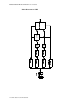
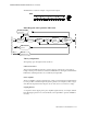
The bandpass stage contains a bandpass filter for the modulated signals coming in from the
photo-amplifier. This filters out noise outside a passband centred on the modulation
frequency.
9DULDEOH* DL Q
This section amplifies the incoming signals. The gain is set by a digital to analog converter
(DAC) which allows 512 gain settings.
$QDORJWR'LJLWDO&RQYHUWHU$'&
This is a 12-bit converter. Oversampling is used to get the required resolution. To optimize
the ADC input voltage, the variable gain adapts accordingly to the signal quality.
'LJLWDO6LJQDO3URFHVVRU'63
The DSP demodulates and filters the signal from the ADC, and passes it on to the SpO
2
ASIC.
6HOI7HVW6LJQDO*HQHUDWRU
This generates a wave that is similar to a patient signal. It is processed through the complete
circuitry starting at the photo amplifier stage. Just before the processing of the patient signal
begins, the test signal is switched on to check correct functioning of the circuitry.
5&RGH0HDVXUHPHQW&LUFXLW
This circuit measures the coding resistor of the transducer, digitizes it, and sends it to the
SpO
2
CPU.
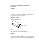
Each transducer has coding resistors in the connector, so that it can be identified by this
measurement.
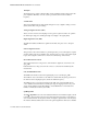
&385205$0DQG$6,&
The $6,& is the interface between the digital signal processor and the SpO
2
CPU.
The ASIC also acts as an interface to the ADC and contains all the frequency generators for
the ADC clock, the sampling frequency and the modulation frequency. .
The &38gets the processed SpO
2
signal from the ASIC, and controls the LED current
source, the RCode measurement, the variable gain stage, the clipping detection, the power
supply, and the Self-Test circuit. The CPU also detects INOP and error information and
handles communication with the system CPU.
6S2
$OJRULWKP
The6S2
$OJRULWKP receives the demodulated and filtered red and infrared signals, and the
transducer coding information from the SpO
2
measurement frontend. The red and infra-red
wave is transformed into the frequency domain. An adaptive signal analysis of the frequency
information eliminates artifact and noise from the patient signal that is then used to calculate