
User`s guide

M3000A/M3046A/M3015A/M3016A Service Guide
Introduction to the Instrument 1-31
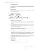
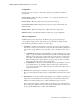
This illustration contains an example of a typical wave in SpO
2
.
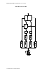
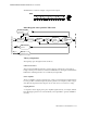
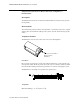
%ORFN'LDJUDPRIWKH6S2
3/(7+&LUFXLW
7KHRU\RI2SHUDWLRQ
The signals progress through the circuit as follows:
/('&XUUHQW6RXUFH
This generates the LED current from a constant voltage provided by the power supply. A
bridge consisting of four transistors switches the LED current for driving the red and infrared
LEDs. These switching transistors are controlled by the SpO
2
CPU.
3KRWR$PSOLILHU
The photo amplifier is an active input current to voltage converter. The input signal is filtered
by a low pass filter to eliminate higher frequencies generated, for example, by electro-surgery
units. Then the input current from the photo diode of the sensor is converted to a voltage.
&OLSSLQJ'HWHFWRU
A comparator detects clipping of the photo-amplifier signal caused by, for example, ambient
light. The clipping detection is connected directly to the SpO2 CPU to generate an INOP if
necessary.
3OHWK
7R)URP6S27UDQVGXFHU
photo
LED
Rtype/
Rlambda
Self-Test Signal
Generator
Photo
Clipping
Detector
LED Current
Source
RCode
Measurement
Var iabl e
Gain
ADC
Digital
Signal
Processor
CPU
ROM/RAM
ASIC
current
current
7R)URP6\VWHP&38
Bandpass
Amplifier