
User`s guide


M3000A/M3046AM3015A/M3016A Service Guide
1-24 Introduction to the Instrument
6DIHW\
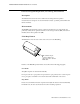
To ensure the safety of the patient, the patient-applied parts are isolated from ground by
optical isolators and a transformer. The circuit is also encapsulated in plastic.
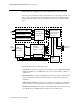
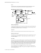
%ORFN'LDJUDPRIWKH(&*5HVS
7KHRU\RI2SHUDWLRQ
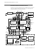
As ECG and Resp signals pass from the patient to the Monitor, they progress through stages
corresponding to the logical sections of the circuit, as shown in the block diagram. Circuit-
related faults can generally be isolated to one of the stages.
7UDQVGXFHU
Signals are received through patient electrodes and lead cables via the input connector.
,QSXW3URWHFWLRQ1HWZRUN
The Input Protection Network and ESU filter eliminate extraneous signals. This protects the
rest of the circuitry from defibrillator voltages, high frequency interference signals, and
electrostatic discharges.
(&*$6,&
The signals are processed by the ECG Application-Specific Integrated Circuit (ECG ASIC)
which has an input amplifier with a fixed gain for each of the four electrodes. They are then
passed to a digital-to-analog converter (D/A Converter) for offset compensation and then to
an analog-to-digital converter (A/D Converter). The input/output logic (which is controlled
from the CPU) controls the analog-to-digital conversion and reads out the digitized ECG
data. The CPU communicates with the ECG ASIC via a built-in serial link.
To prevent interference from the 50/60Hz power line, the common mode signal is used to
drive the right leg (RL) drive amplifier. The output from the amplifier is then returned to the
patient via the RL electrode.
Input
Protection
Network
ECG
CPU
ROM/RAM
C
RA
LA
LL
RL
Bridge &
Amplifier
Demodulator
ECG
Electrodes
Respiration
To/From
System CPU
Excitation
Current
Source
From
Patient
ASIC