
User`s guide


M3000A/M3046AM3015A/M3016A Service Guide
1-22 Introduction to the Instrument
Functional Description of the Measurement Server Hardware
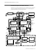
The Server receives information signals (such as ECG, etc.) from the patient, performs some
data processing, then transmits the data to the Monitor via the Server-to-Monitor link bar.
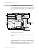
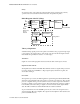
The following block diagram shows the main functional components of the Measurement
Server.
The main functional areas are summarized below.
&38%RDUG—Consisting of a 68360 Controller, the Memory System (Flash ROM, SRAM,
DRAM, ASIC, RTC, etc.), the NBP A/D Converters, and a connector link to a Monitor or
an Extension.
• )URQW(QG%RDUG—Consisting of the ECG/Resp Front End, the SpO
2
Front End, the Press/
Temp Front End and the Floating/Non-Floating Isolation area all feeding signals to the
CPU Board.
• 1%33QHXPDWLF$VVHPEO\²Connecting to the DC/DC Converter Board, the Pneumatic
Power Switches housed in the DC/DC Converter Boardand to the NBP A/D Converters.
• '&'&&RQYHUWHU%RDUG²Connecting to the Floating/Non-Floating Isolation area on the
Front End Board, to the NBP Pneumatic Assembly and to the CPU System.
From
Patient
CPU System
(68360, Flash-ROM
3.3V
SRAM, DRAM,
ASIC, RTC,...)
Floating /
Non-Floating
Isolation
ECG/Resp Front End
SpO
2
Front End
Press/Temp Front End
5V
+12V
3.3V (Buffd.)
48V
78kHz
DC/DC
Converter
Board
Pneumatic
Power Switches
-12V
14Vac
12V
NBP
Pneumatic
Assembly
+12V
-12V
NBP
A/D
Converters
To/From
Monitor
6Vac
6Vac
-6Vac
48V
78kHz
Serial Link
Link Bar
CPU Board
Front End Board
From
Patient