
User`s guide


M3000A/M3046AM3015A/M3016A Service Guide
1-16 Introduction to the Instrument
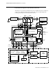
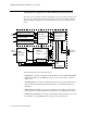
The main functional areas are summarized in the following:
• 6\VWHP%RDUG²Comprising a 68360 Controller, the Memory System, the Video System,
LAN (network) connector link to Server, ECG-Out, Human Interface and DC/DC Con-
verter.
• &RQQHFWRU%RDUG²Connecting the System Board to the AC Power Supply and battery.
The LAN (network) filter and connector, the VGA connector and the Alarm Relay Output
(Nurse Call) are located on the Connector Board. The Connector Board has a 48-pin con-
nector to the System Board.
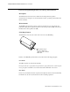
• 'LVSOD\$VVHPEO\²Comprising a 6.5 inch TFT color LCD display (including 2 backlight
tubes), the Display Adapter Board and the associated backlight inverter board (generates
the high voltage for the tubes). These parts are packed into a soft, rubber-based holder
(sometimes referred to as the FXVKLRQ). (Note: The LCD display uses WKLQILOPWHFKQRORJ\
and is sometimes referred to as a 7)7 display.)
The Display Assembly connects to the System Board via a 40-wire flat ribbon cable.
• %H]HO$VVHPEO\²Comprising the U-shaped TouchStrip, the Keyboard (which includes
operating keys, alarm LEDs, On/Off switch and AC and battery indicator LEDs), and the
IrDA Board (infrared printer interface).
The Bezel Assembly connects to the System Board via a 34-wire flat ribbon cable.
• 6SHDNHU²Connected to the System Board with a 2-wire cable. The loudspeaker provides
the audible output for alarms, and audible feedback when the user presses a manual control.
• $&3RZHU6XSSO\²Connected to the Connector Board to power the Instrument and/or
charge the battery depending on the operating mode.
• 6PDUW%DWWHU\²As an option, a standard, intelligent battery with an I2C interface to the
DC/DC controller.
• :LUHOHVV/$1$VVHPEO\² Comprising the Wireless LAN CPU Board and the radio fre-
quency (RF) Board. The Wireless LAN Assembly connects to the System Board via a 140-
pin extension connector. The RF Board connects to the antenna, which is built into the
monitor handle via a coax cable.
9HQWLODWRU)DQ² Connected to the System Board with a 2-wire cable. The fan controls
the temperature inside the Monitor when the Wireless LAN option is installed.
Detailed descriptions are given in the following sections.
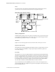
'LVSOD\9LGHR&RQWUROOHU
The Display Video Controller runs the software that controls the display. This software
processes the high level display command to generate and format the screen characters,
graphics, and wave plots, and also generates the video control signals for the LCD display.
The software continuously checks the functionality of the hardware in the Display Controller,
and issues an error indication in the event of a hardware malfunction.