
User`s guide


M3000A/M3046A/M3015A/M3016A Service Guide
Introduction to the Instrument 1-15
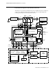
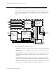
Functional Description of the Monitor Hardware
The Monitor receives data from the Measurement Server and Measurement Server Extension
via the Server-to-Monitor link bar and presents this data on the color LCD display. The
following block diagram shows the main functional areas.
$&
3RZHU6XSSO\
AC
6PDUW%DWWHU\
Optional
Vbat,
I2C
LAN
&RQQHFWRU
%H]HO$VVHPEO\
.H\ERDUG
TouchStrips
,U'$
Standby On/Off (PIC)
4 hardkeys(HIF)
LEDs:
X Bell(HIF)
red alarm(HIF)
yellow alarm(HIF)
On/Off(+5V)
AC Power(PIC)
Battery(PIC)
'LVSOD\$GDSWHU
%RDUG
,QYHUWHU%RDUG
/&'
'LVSOD\
%DFNOLJKW
48 Pin
DC/DC Converter
48V current limiter
Battery charger
Display
ECG
Out
SRL to
Measurement
CPU System(360)
(Flash,SRAM,DRAM)
HIF(83C552)
(TouchStrip,Keys,Sound,
LEDs, Alarm Relay,
Battery)
34 Wire
40 Wire
Processor (Battery
6 Pin
2x2 Pin
31 Pin
Flat Cable
Flat Cable
cable
Flex
cable
Connector
6 Pin
Connector
5 Pin
Connector
48V,
AC present
(Network)
SRL
LAN
Serial Link
uP bus
Video
I2C
Rx,Tx
TouchStrip
Keys
Alarm LEDs
PIC LEDs,Standby
Vbat 48V
AC
present
I2C
%RDUG
(Infrared)
'LVSOD\$VVHPEO\
Video
Controller
Controller)
Server
Alarm
Relay
VGA
(M3000A)
48Vlim +5V Vbuf
ECG Out/
Marker In
Controller
6\VWHP%RDUG
Ventilator
Fan
Optional
Connector
140 Pin