
User`s guide


M3000A/M3046A/M3015A/M3016A Service Guide
5-6 Troubleshooting the Instrument
7URXEOHVKRRWLQJWKH6\VWHP%RDUG/('V
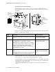
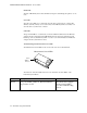
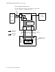
Switch the Monitor off then on again to observe the System Board LEDs. These can be
viewed through the top left corner of the rear panel. (You need to remove the Server to view
these LEDs).
The meaning of the System Board LEDs is given in the following table together with a brief
summary of possible defect conditions.
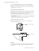
An ECG OUT LED is also located on the System Board and can be viewed after removing
the Power Supply cover. The meaning of the ECG OUT LED is as follows:
• When permanently on (>20 seconds), this LED indicates an error in the ECG_OUT section.
• If a single fatal error in the ECG_OUT section is detected during power-on, the ECG OUT
LED switches on for up to 20 seconds.
The ECG OUT LED switches off if this fatal error cannot be detected again after 20 sec-
onds.
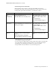
LED Description Defect Condition
Green +5V power LED. When on, indicates the presence
of +5V.
Off: Check Power Supply
and associated cabling.
Yellow Main CPU status LED—When on and blinking,
this LED indicates normal CPU operation.
This LED starts to blink 2 times per second after
the red Error LED switches off then slows to blink
1 time per second after the red Error LED
switches off when the system boot has finished
(approximately 2 seconds).
If permanently on or off,
indicates a hung CPU.
Red Error LED—When on, this LED indicates an
error.
This LED switches on for about 1 second after the
System Board has been reset then switches off.
If permanently on, the Sys-
tem Board is probably defec-
tive.
View (x3)
System Board
LEDs
Gr
e
en
Y
el
l
o
w
R
ed
View (x1)
System Board
LED (ECG OUT)
Remove
Power Supply
Cover