Programming Guide Agilent Technologies Series 66lxxA MPS Power Modules Agilent Part No. 5959-3362 Microfiche Part No.
Safety Guidelines The beginning of the Users Guide for GPIB Power Modules Series 66lxxA has a Safety Summary page. Be sure you are familiar with the information on that page before programming the power module for operation from a controller. Printing History The current edition of this guide is indicated below. Reprints of this guide containing minor corrections and updates may have the same printing date. New editions are identified by a new printing date and, in some cases, by a new part number.
Contents 1. Introduction About this Guide ..........................................................................................................................................7 Documentation Summary .............................................................................................................................7 External References......................................................................................................................................
Related Commands.....................................................................................................................................23 Order of Presentation .................................................................................................................................23 Common Commands ..................................................................................................................................23 Subsystem Commands.......................................
OUTP:DFI:LINK .................................................................................................................................40 OUTP:DFI:SOUR ................................................................................................................................40 OUTP:PROT:CLE ...............................................................................................................................40 OUTP:PROT:DEL ...............................................................
Location of Event Handles .........................................................................................................................54 Initial Conditions at Power On ...................................................................................................................55 Status Registers .......................................................................................................................................55 The PON Bit...............................................
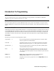
1 Introduction About This Guide You will find the following information in the rest of this guide: Chapter 2 Chapter 3 Chapter 4 Chapter 5 Chapter 6 Appendix A Appendix B Introduction to SCPI messages structure, syntax, and data formats. Examples of SCPI programs. Dictionary of SCPI commands. Table of module programming parameters. Description of the status registers. Description of synchronizing outputs with triggers and lists. Error messages. SCPI conformance information.
VXIplug&play Power Products Instrument Drivers VXIplug&play instrument drivers for Microsoft Windows 95 and Windows NT are now available on the Web at http://www.agilent.com/find/drivers. These instrument drivers provide a high-level programming interface to your Agilent Technologies electronic load. VXIplug&play instrument drivers are an alternative to programming your instrument with SCPI command strings.
2 Introduction To Programming GPIB Capabilities Of The Power Module All power module functions except for setting the GPIB address are programmable over the GPIB. The IEEE 488.1 capabilities of the power module are listed in the User’s Guide. Module GPIB Address The power module operates from a primary GPIB address that is set by a switch on the mainframe. The power module’s secondary GPIB address is determined by its slot position within the mainframe. See the mainframe Installation Guide for details.
Types of SCPI Messages There are two types of SCPI messages, program and response. • A program message consists of one or more properly formatted SCPI commands sent from the controller to the power module. The message, which may be sent at any time, requests the power module to perform some action. • A response message consists of data in a specific SCPI format sent from the power module to the controller.
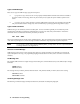
Figure 2-1. Command Message Structure The basic parts of the above message are: Message Component Headers Header Separator Data Data Separator Message Units Message Unit Separator Root Specifier Query Indicator Message Terminator Example VOLT LEV PROT CURR The colon in VOLT:LEV 8.0 8.8 The space in VOLT 8. 0 and PROT 8. 8 VOLT:LEV 8.0 PROT 8.8 CURR? The semicolons in VOLT: LEV 8. 0; and PROT 8. 8; The colon in PROT 8. 8; : CURR? The question mark in CURR? The (newline) indicator.
The SCPI interface is not sensitive to case. It will recognize any case mixture, such as TRIGGER, Trigger, TRIGger, triGgeR. Note Shortform headers result in faster program execution. Header Convention. In this manual, headers are emphasized with boldface type. The proper short form is shown in upper-case letters, such as DELay. Header Separator. If a command has more than one header, you must separate them with a colon (VOLT: PROT OUTPut:RELay:POLarity). Optional Headers.
Traversing the Command Tree Figure 2-2 shows a portion of the subsystem command tree (you can see the complete tree in Figure 3-2). Note the location of the ROOT node at the top of the tree. The SCPI interface is at this location when: • • • • The power module is powered on. A device clear (DCL) is sent to the power module. The interface encounters a message terminator. The interface encounters a root specifier. Figure 2-2.
The optional header SOURCE precedes the current, list, and voltage subsystems (see Figure 3-2). This effectively makes :CURRENT, :LIST, and :VOLTAGE root-level commands. Note The optional Agilent 66001 Keyboard does not display optional headers. Moving Among Subsystems In order to combine commands from different subsystems, you need to be able to restore the active path to the root. You do this with the root specifier (:).
Symbol Table 2-1. Numerical Data Formats Data Form Talking Formats Digits with an implied decimal point assumed at the right of the least-significant digit. Examples: 273 0273 Digits with an explicit decimal point. Example: 273. .0273 Digits with an explicit decimal point and an exponent. Example: 2.73E+2 273.0E-2 Listening Formats Extended format that includes , and . Examples: 273 273. 2.73E2 Expanded decimal format that includes and MIN MAX. Examples: 273 273. 2.
System Considerations The remainder of this chapter addresses some system issues concerning programming. These are power module addressing and the use of the following types of GPIB system interfaces: 1. 2. 3. HP Vectra PC controller with Agilent 82335A GPIB Interface Command Library IBM PC controller with National Instruments GPIB-PCII Interface/Handler Agilent controller with Agilent BASIC Language System Note Some specific application programs are given in Appendix B.
Your application program will not include the power module symbolic name and GPIB address. These must be specified during configuration (when you run IBCONF.EXE). Note that the primary address range is from 0 to 30 but any secondary address must be specified in the address range of 96 to 126. The power supply expects a message termination on EOI or line feed, so set EOI w/last byte of Write. It is also recommended that you set Disable Auto Serial Polling.
Using the National Instruments GPIB Interface • • • • • • When CALLs are made to the GPIB driver, all parameters are passed as variables. The module is identified as a device in two ways. First, the GPIB.COM driver is modified to include the module. Use the mainframe address as the primary bus address and the slot address as the secondary address. The driver requires secondary address 0 (which is for slot 0) to be entered as 96, secondary address 1 to be entered as 97, etc.
Sending Commands to and Receiving Data from the Module Sending the Command “VOLT 5” ********************************************** Agilent BASIC ************************************************ 2100 2110 2120 OUTPUT 70501;"VOLT 5" ! where 70501 means 7 is the select code of the GPIB interface 05 is the ! GPIB address of the mainframe, 01 is the slot number (secondary address) ! of the module ************************* GWBASICAgilent ( 82335A/82990A/61062B GPIB Command Library) ************************ 2100
Receiving Data from the Module The following screens show how to enter data from the module with various interfaces.
***************** Microsoft C (Agilent 82335A/82990A/61062B GPIB Command Library) ********************* /* Assumes that you have an error handler routine, called ’error_handler’ that accepts a float. The error handler is then passed the float that is returned from each call to the library. */ #include & #include k #include &
3 Language Dictionary Introduction This section gives the syntax and parameters for all the IEEE 488.2 SCPI commands and the Common commands used by the Agilent Series 66l0xA power modules. It is assumed that you are familiar with the material in "Chapter 2 - Introduction to Programming". That chapter explains the terms, symbols, and syntactical structures used here and gives an introduction to programming. The programming commands function the same way in all Agilent Series 66l0xA power modules.
Description Of Common Commands Figure 3-1 shows the common commands and queries. These commands are listed alphabetically in the dictionary. If a command has a corresponding query that simply returns the data or status specified by the command, then both command and query are included under the explanation for the command. If a query does not have a corresponding command or is functionally different from the command, then the query is listed separately.
• If *CLS immediately follows a program message terminator (), then the output queue and the MAV bit are also cleared. Command Syntax *CLS Parameters (None) Query Syntax (None) *ESE Meaning and Type Event Status Enable Device Status Description This command programs the Standard Event Status Enable register bits. The programming determines which events of the Standard Event Status Event register (see *ESR?) are allowed to set the ESB (Event Summary Bit) of the Status Byte register.
*IDN? Identification Query Meaning and Type Identification System Interface Description This query requests the power module to identify itself. It returns a string composed of four fields separated by commas. Query Syntax Returned Parameters Example Related Commands *IDN? Field Information Agilent Technologies Manufacturer xxxxxA 5-digit model number followed by a letter nnnnA-nnnnn 10-character serial number or 0 .xx.xx Revision levels of firmware Agilent Technologies,66101A,0,A.00.
Do not follow *OPC? with *TRG or GPIB bus triggers. Such triggers sent after *OPC? will be prevented from executing and will prevent the power module from accepting further commands. If this occurs, the only programmable way to restore operation is by sending the power module a GPIB DCL (Device Clear) command. Query Syntax Returned Parameters Related Commands *OPC? ASCII 1 is placed in the Output Queue when the power module has completed operations.
*RCL Meaning and Type Recall Device State Recalling a previously stored state may place hazardous voltage at the power module output. Description This command restores the power module to a state that was previously stored in memory with a *SAV command to the specified location.
Command Syntax Parameters Query Syntax Related Commands *RST (None) (None) *PSC *SAV *SAV Meaning and Type Save Device State Description This command stores the present state of the power module to a specified location in memory. Up to 10 states can be stored. Storage locations 0 through 4 are in nonvolatile memory and locations 5 through 9 are in volatile memory. If a particular state is desired at power on, it should be stored in location 0.
If *PSC is programmed to 0, then the *SRE command causes a write cycle to nonvolatile memory. The nonvolatile memory has a finite number of write cycles (see Table 1-2 in the power module User’s Guide). Programs that repeatedly write to nonvolatile memory can eventually exceed the maximum number of write cycles and may cause the memory to fail.
*TST? Meaning and Type Test Device Test Description This query causes the power module to do a self-test and report any errors (see "Selftest Error Messages" in Chapter 3 of the power module User’s Guide). Query Syntax Returned Parameters Related Commands *TST? 0 Nonzero (None) Indicates power module passed self-test. Indicates an error code.
Figure 3-2. Subsystem Tree Diagram Calibration Subsystem The commands in this subsystem allow you to do the following: • Control automatic calibration of the measurement subsystem. • Enable and disable the calibration mode. • Change the calibration password. • Calibrate the overvoltage protection (OVP) circuit. • Calibrate the current and voltage output levels, and store new calibration constants in nonvolatile memory.
Whenever CAL:AUTO ONCE is sent, the power module performs an immediate readback temperature compensation. CAL:AUTO ONCE is a sequential command that takes several seconds to complete. When CAL:AUTO ON is sent, the power module automatically performs a readback temperature compensation before executing every MEAS command. Use of this command extends the execution time of every MEAS query.
CAL:SAVE This command can only be used in the calibration mode. It saves any new calibration constants (after a current or voltage calibration procedure has been completed) in nonvolatile memory. Command Syntax: Parameters Examples Query Syntax Related Commands CALibrate:SAVE (None) CAL:SAVE (None) CAL:CURR CAL:VOLT CAL:STAT CAL:STAT This command enables and disables the calibration mode.
CAL:VOLT:PROT This command can only be used in the calibration mode. It calibrates the power module overvoltage protection (OV) circuit. The power module output must be enabled and operating in the constant voltage (CV) mode. The power module automatically performs the calibration and stores the new OV constant in nonvolatile memory. CAL:VOLT:PROT is a sequential command that takes several seconds to complete.
CURR:PROT:STAT This command enables or disables the power module overcurrent (OC) protection function. If the overcurrent protection function is enabled and the power module goes into constant current (CC) mode, then the output is disabled and the Questionable Condition status register OC bit is set (see "Chapter 4 - Status Reporting"). An overcurrent condition can be cleared with the OUTP:PROT:CLE command after the cause of the condition is removed.
Command Syntax Parameters *RST Value Examples Query Syntax Returned Parameters Related Commands INITiate[:IMMediate] INITiate:CONTinuous For INIT[:IMM] (None) For INIT:CONT 0 | 1 | OFF | ON OFF INIT INIT:CONT 1 INIT:CONT ON For INIT[:IMM] (None) For INIT:CONT INITiate:CONTinuous? 0|1 ABOR CURR:TRIG TRIG *TRG VOLT:TRIG List Subsystem This subsystem controls the generation of parameter lists that sequence the power module output through values of voltage and current.
LIST:CURR:POIN? This query returns the number of points specified in LIST:CURR. Note that it returns only the total number of points, not the point values. Query Syntax [SOURce]:LIST:CURRent:POINts? Returned Parameters Example LIST:CURR:POIN? Related Commands CURR:MODE LIST:CURR LIST:DWEL LIST:DWEL This command sets the dwell points for the output current list and output voltage list.
LIST:VOLT This command specifies the output voltage points in a list. The voltage points are given in the command parameters, which are separated by commas. Up to 20 points may be entered and the output voltage values specified by the points will be generated in the same order as they were entered. Command Syntax Parameters Default Suffix Examples Query Syntax Related Commands [SOURce]:LIST:VOLTage {,} See Table 3-2 V LIST:VOLT 2.0,2.5,3.0 LIST:VOLT MAX,2.
Command Syntax Parameters *RST Value Examples Query Syntax Returned Parameters Related Commands OUTPut[:STATe] [,NORelay] 0 | OFF[,NORelay] | 1 | ON[,NORelay] 0 OUTP 1 OUTP:STAT ON,NORELAY OUTPut[:STATe]? 0|1 *RCL *SAV OUTP:DFI This command enables or disables the discrete fault indicator (DFI) signal to the power module backplane.
OUTP:PROT:DEL Sets the delay time between the programming of an output change that produces a CV, CC, or UNREG condition and the recording of that condition by the Status Operation Condition register. The delay prevents momentary changes in power module status that can occur during reprogramming from being registered as events by the status subsystem. Since the delay applies to CC status, it also delays the OCP (overcurrent protection) feature.
OUTP:TTLT This command enables or disables the power module Trigger Out signal, which is available at a BNC connector on the rear of the mainframe. Trigger Out is the logical OR of all the power module TTLTrig signals (see "Chapter 5 - Synchronizing Power Module Output Changes"). It also may be selected as a trigger input (see TRIGger:SOURce).
Status Operation Registers The bit configuration of all Status Operation registers is shown in the following table: Bit Configuration of Operation Registers 11 10 9 8 7 6 5 4 3 2 1 Bit Position 12 STC NU CC NU CV NU NU WTG NU NU NU NU Bit Name 4096 2048 1024 512 256 128 64 32 16 8 4 2 Bit Weight CAL = Interface is computing new calibration constants; CC = The power module is in constant current mode; CV = The power module is in constant voltage mode; NU = (Not used); STC = The list step is complete; WTG = I
STAT:OPER:NTR|PTR Commands These commands set or read the value of the Operation NTR (Negative-Transition) and PTR (Positive-Transition) registers. These registers serve as polarity filters between the Operation Enable and Operation Event registers to cause the following actions: • • • • Note When a bit in the Operation NTR register is set to 1, then a 1-to-0 transition of the corresponding bit in the Operation Condition register causes that bit in the Operation Event register to be set.
STAT:QUES? This command returns the value of the Questionable Event register. The Event register is a read-only register which holds (latches) all events that are passed by the Questionable NTR and/or PTR filter. Reading the Questionable Event register clears it.
Command Syntax Parameters Suffix Default Value Example Query Syntax Returned Parameters Related Commands STATus:QUEStionable:NTRansition STATus:QUEStionable:PTRansition 0 to 32727 (None) 0 STAT:QUES:NTR 16 STAT:QUES:PTR 512 STATus:QUEStionable:NTRansition? STATus:QUEStionable:PTRansitiion? (Register value) STAT:QUES:ENAB SYST:ERR? This query returns the next error number followed by its corresponding error message string from the remote programming error queue.
Command Syntax Parameters Examples Query Syntax Related Commands TRIGger[:STARt][:IMMediate] (None) TRIG TRIG: IMM (None) ABOR CURR:MODE CURR:TRIG VOLT:MODE VOLT:TRIG INIT *TRG TRIG:DEL This command sets the time delay between the detection of an event on the specified trigger source and the start of any corresponding trigger action on the power module’s output.
Voltage Subsystem This subsystem programs the output voltage of the power module. VOLT This command directly programs the immediate voltage level of the power module. The immediate level is the voltage applied at the output terminals. This command is always active, even when the voltage subsystem is in the list mode (see VOLT:MODE).
Query Syntax Returned Parameters Related Commands [SOURce]:VOLTage:PROTection [:LEVel]? [SOURce]:VOLTage:PROTection [:LEVel]? MIN [SOURce]:VOLTage:PROTection [:LEVel]? MAX VOLT:PROT? returns presently programmed OVP level. VOLT:PROT? MAX and VOLT:PROT? MIN return the maximum and minimum programmable OVP levels. OUTP:PROT:CLE *RST *SAV *RCL VOLT:SENS:SOUR? This command reads the state of the power module output connector remote sense switch.
Table 3-1.
4 Status Reporting Power Module Status Structure Figure 4-1 shows the status register structure of the power module. The Standard Event, Status Byte, and Service Request Enable registers and the Output Queue perform standard GPIB functions as defined in the IEEE 488.2 Standard Digital Interface for Programmable Instrumentation. The Operation Status and Questionable Status registers implement status functions specific to the power module.
Bit Signal 0 CAL 5 8 WTG CV 10 CC 12 DWE Table 4-2.
Figure 4-1. Power Module Status Model Standard Event Status Group Register Functions This group consists of an Event register and an Enable register that are programmed by COMMON commands. The Standard Event register latches events relating to interface communication status (see Table 4-2). It is a read-only register that is cleared when read. The Standard Event Enable register functions similarly to the enable registers of the Operation and Questionable status groups.
Status Byte Register This register summarizes the information from all other status groups as defined in the IEEE 488.2 Standard Digital Interface for Programmable Instrumentation standard. The bit configuration is shown in Table 4-2. The register can be read either by a serial poll or by *STB?. Both methods return the same data, except for bit 6. Sending *STB? returns MSS in bit 6, while polling returns RQS in bit 6.
Initial Conditions At Power On Status Registers When the power module is turned on, a sequence of commands initializes the status registers. Table 4-4 shows the register states and corresponding power-on commands for the factory-default *RST power-on state. If the module power-on function switch is set to 0, then the power-on state is determined by the parameters stored in location 0 (see Chapter 4 of the User’s Guide). Table 4-4.
Table 4-5. Generating RQS from the CC Event Register Operation PTR Command STAT:OPER:PTR 1024 Operation Enable STAT:OPER:ENAB 1024 Service Request Enable *SRE 128 Operation Condition STAT:OPER:EVEN? Comment Allows a positive transition at the CC input (bit 10) to be latched into the Status Event register. 1 Allows the latched CC event to be summed into the OPER summary bit. Enables the OPER summary bit from the Status Byte register to generate RQS.
5 Synchronizing Power Module Output Changes Introduction If you use only the VOLT [: LEV] : TRIG and/or CURR [: LEV] : TRIG commands to trigger output changes, you do not need the information in this chapter. This chapter gives supplemental information on how you can synchronize power module output changes to internal or external events. The output changes can be: • A change in output voltage level. • A change in output current level.
Idle State When the power module is turned on, the trigger subsystem is in the idle state. In this state, the trigger subsystem ignores all triggers. When the trigger action has been completed, the trigger subsystem returns to this state. It also returns to the Idle state if the ABORt command or an implied ABORt command (*RST, *RCL, or any LIST) is sent. Initiated State The INITiate command moves the trigger subsystem from the Idle state to the Initiated State.
Output Change State When the trigger subsystem enters the Output Change state, the output voltage and current are set to the pending levels programmed by the VOLTage:TRIGgered and CURRent:TRIGgered commands. Once this occurs, the existing triggered levels are cleared and must be reprogrammed. If no triggered levels are programmed, then the trigger has no effect on the output levels. When the triggered actions are completed, the trigger subsystem returns to the Idle state.
Signal DWE LSC RTG TDC STC STS WTG Table 5-1. Trigger Subsystem Status and Event Signals Type Description Status Bit Dwelling. True only during the dwelling state. DWE can be monitored at the Operation Status register (see "Chapter 4 - Status Reporting"). Event Handle List Sequence Complete. Occurs upon exit from the Dwelling state after the last programmed list point has been executed. If LIST: COUNt is greater than 1, LSC occurs once for each count until the list is done.
List Subsystem The List Subsystem commands allow you to program a sequence of voltage and/or current values that will be applied to the power module output when it is the list mode (VOLTage:MODE LIST or CURRent:MODE LIST). Up to 20 voltage and current values, with 20 associated time intervals (dwells), may be programmed. By using lists, you can program a complex sequence of power module outputs with minimal interaction between the controller and the power module.
The number of dwell points must equal the number of output points: LIST:VOLT 3.0,3.25,3.5,3.75 LIST:DWEL 10,10,25,40 The only exception is for a dwell list with one value, which gives the same interval to all the points in the corresponding voltage or current list. Note Sending a VOLT [: LEV: IMM] or CURR [: LEV: IMM] command during an interval will override the list output value for that interval. When the next interval begins, the output will be determined by the list value for that interval.
Figure 5-3.
DFI (Discrete Fault Indicator) Subsystem Whenever a fault is detected in the power module, it is capable of generating a low-true TTL signal at the mainframe FLT jack for communication with external devices (see “INH/FLT Characteristics” in Chapter 1 of the Agilent 66000A Installation Guide for the electrical parameters). The source for the DFI signal can be any of the parameters of the OUTPut:DFI:LINK command (see Table 3-1).
6 Error Messages Power Module Hardware Error Messages Front panel error messages resulting from selftest errors or runtime failures are described in the power module User’s Guide. System Error Messages System error messages are read back via the SYST:ERR? query. The error number is the value placed in the power module error queue. SYST:ERR? returns the error number into a variable and combines the number and the error message into a string.
Error Number -222 -223 -241 -310 -330 -350 -400 -410 -420 -430 -440 66 Table 6-1. Summary of System Error Messages (continued) Error String [Description/Explanation/Examples] Data out of range [e.g.
A SCPI Conformance Information Note See Chapter 3 - Language Dictionary for command syntax. SCPI Version This power module conforms to Version 1990.0.
Non-SCPI Commands CAL:CURR CAL:PASS CAL:SAVE CAL:VOLT OUTP:DFI[:STAT] OUTP:DFI[:STAT]? OUTP:DFI:LINK OUTP:DFI:LINK? OUTP:DFI:SOUR 68 OUTP:DFI:SOUR? OUTP:REL[:STAT] OUTP:REL[:STAT]? OUTP:REL:POL OUTP:REL:POL? [SOUR]:LIST:STEP [SOUR]:LIST:STEP? [SOUR]:VOLT:SENS? SCPI Conformance Information
B Application Programs This section contains seven example applications. For each application, there is: • • • • • • • An overview of the application. Which MPS features are used to implement the application. The advantages and benefits of the MPS solution. The details of the implementation of the solution. A block diagram of the setup. A sample program listing in Agilent BASIC. A description of variations on the application.
Application 1. Sequencing Multiple Modules During Power Up Overview of Application When testing mixed signal devices, ± bias supply voltages are typically applied before logic bias supply voltages. For a device that is sensitive to when bias voltages are applied, the order of power up of multiple power modules can be controlled. For this example, the device requires three bias supplies, + 5 V for the logic circuits and ± 15 V for amplifier circuits.
Module in slot 2: The module is connected to + 5 V on the DUT. The initial voltage setting is 0 V. The module listens for a backplane TTL Trigger. The trigger delay is programmed to 50 ms. Upon receipt of the trigger, the module waits the trigger delay time and then goes to 5 V. Variations On This Implementation 1. The modules could be set to generate SRQ when the last module (+ 5 V) reaches its final output value.
Figure B1-2.
10 20 30 40 50 60 70 80 90 100 110 120 130 140 150 160 170 180 190 200 210 220 230 240 250 260 270 280 290 300 310 320 330 340 350 360 370 380 390 400 410 420 430 440 450 460 470 480 490 500 510 520 530 540 550 ! APPLICATION #1: SEQUENCING MULTIPLE MODULES DURING POWER UP ! PROGRAM: APP_1 ! ASSIGN @Slot0 TO 70500 ! SELECT CODE 7, MAINFRAME ADDRESS 05, SLOT 00 ASSIGN @Slot1 TO 70501 ! SELECT CODE 7, MAINFRAME ADDRESS 05, SLOT 01 ASSIGN @Slot2 TO 70502 ! SELECT CODE 7, MAINFRAME ADDRESS 05, SLOT 02 ! ! SET U
Application 2. Sequencing Multiple Modules to Power Down on Event Overview Of Application When testing devices, such as some GaAs and ECL devices that are sensitive to when bias voltages are removed, the order of power-down of multiple power modules can be controlled. The power-down sequence can be initiated by an event, such as a change in power module status, fault condition, detection of a TTL signal, etc. For this example, there are three supplies + 5 V and ± 15 V.
MPS Set Up Module in slot 0: The module is connected to + 15 V on the DUT. The initial voltage setting is 15 V. The module monitors its status. The module will generate a backplane TTL Trigger on CV-to-CC crossover. The module listens for a backplane TTL Trigger. The trigger delay is programmed to 15 ms. Upon receipt of the trigger, the module waits the trigger delay time and then goes to 0 V. Module in slot 1: The module is connected to supply - 15 V to the DUT.
Figure B2-1. Block Diagram of Application #2 Figure B2-2.
10 20 30 40 50 60 70 80 90 100 110 120 130 140 150 160 170 180 190 200 210 220 230 240 250 260 270 280 290 300 310 320 330 340 350 360 370 380 390 400 410 420 430 440 450 460 470 480 490 500 510 520 ! APPLICATION #2: SEQUENCING MULTIPLE MODULES TO POWER DOWN ON EVENT ! PROGRAM: APP_2 ! ASSIGN @Slot0 TO 70500 ! SELECT CODE 7, MAINFRAME ADDRESS 05, SLOT 00 ASSIGN @Slot1 To 70501 ! SELECT CODE 7, MAINFRAME ADDRESS 05, SLOT 01 ASSIGN @Slot2 TO 70502 ! SELECT CODE 7, MAINFRAME ADDRESS 05, SLOT 02 ! ! SET UP MOD
Application 3. Controlling Output Voltage Ramp Up at Turn On Overview Of Application When control over the rate of voltage ramp up at turn-on of the power module output is required, the desired shape can be approximated by downloading and executing a series of voltage and dwell time points. For this example, you need to program the power module to change its output from 2 volts to 10 volts, slewing through the 8 volt transition in 0.5 seconds. This results in a turn-on ramp-up of 16 V per second.
Figure B3-1. Simulating a Slow Voltage Ramp Figure B3-2. Simulating a Fast Voltage Ramp Variations On This Implementation 1. The module could be set to begin ramping in response to an external or backplane TTL Trigger. 2. The module could be set to generate SRQ when it has finished its transition. This would notify the computer that the voltage is at the proper level.
3. The module could be set to generate an external trigger when it has finished its transition. This trigger could be routed to other instruments as a signal to start making measurements. 4. Multiple modules could be programmed to slew together in response to the computer trigger command. 5. The module could be set to generate an external trigger for each point in the transition. This trigger could be routed to other instruments as a signal to take a measurement at various supply voltages.
10 20 30 40 50 60 70 80 90 100 110 120 130 140 150 160 170 180 190 200 210 220 230 240 250 260 270 280 290 300 310 320 330 340 350 360 370 380 390 400 410 420 430 440 450 460 470 480 490 ! APPLICATION #3: CONTROLLING VOLTAGE RAMP UP AT TURN ON ! PROGRAM: APP_3 ! ASSIGN @Slot0 To 70500 ! SELECT CODE 7, MAINFRAME ADDRESS 05, SLOT 00 ! OPTION BASE 1 DIM V_Step(20) ! ARRAY TO HOLD THE VOLTAGE RAMP STEPS Vstart=2 ! START VOLTAGE FOR RAMP Vstop=10 ! STOP VOLTAGE FOR RAMP Ramp_time=.
Application 4. Providing Time-Varying Voltages Overview of Application To burn-in devices using thermal or mechanical cycling/stress, cyclical time-varying voltage is provided by programming a set of voltage and dwell time points that repetitively sequence over time. For this example, the power module must provide the repetitive waveform shown in Figure B4-1. This time-varying voltage will be applied to a hybrid IC.
MPS Features Used • • • • • • • • • • 20-point voltage List. Repetitive Lists. Dwell time. Dwell-paced Lists. Generate an SRQ on a change in internal status. Disable the output on a change in internal status. Stop the List on a change in internal status. Trigger on a GPIB trigger command. Overcurrent protection. Active downprogramming.
Variations On This Implementation 1. The module could be set to begin generating the waveform in response to an external or backplane TTL Trigger. 2. The module could be set to generate external triggers for each point in the List. This trigger could be routed to other instruments to synchronize external measurements to the change in voltage. (see application #7) Using this technique, parametric measurements could be made on the device during the thermal cycling. 3.
10 20 30 40 50 60 70 80 90 100 110 120 130 140 150 160 170 180 190 200 210 220 230 240 250 260 270 280 290 300 310 320 330 340 350 360 370 380 390 400 410 420 430 440 450 460 470 480 490 500 510 ! APPLICATION #4: PROVIDING TIME-VARYING VOLTAGES ! PROGRAM: APP_4 ! ASSIGN Slot0 TO 70500 ! SELECT CODE 7, MAINFRAME ADDRESS 05, SLOT 00 ! ! INITIALIZE THE MODULE ! OUTPUT @Slot0;"*RST;*CLS;STATUS:PRESET" ! RESET AND CLEAR MODULE OUTPUT @Slot0;”VOLT 0” ! START TEST AT 0 V OUTPUT @Slot0;”CURR .
Application 5. Providing Time-Varying Current Limiting Overview Of Application To provide current limit protection which varies as a function of time, multiple thresholds on current limit are required. Having multiple thresholds can provide a high limit to protect the DUT during its power-up in-rush with automatic switchover to a lower limit to protect the DUT during its steady state operation. For this example, the DUT is a printed circuit assembly.
Figure B5-1. Typical DUT Current vs. Time Figure B5-2. Desired Current vs.
Implementation Details How The MPS Implements The Sequence. The module is programmed to current List mode. The module will execute a dwell-paced current List. The current limit List points are downloaded to the module. The dwell times are downloaded to the module. To begin powering the DUT, the module is triggered by the computer. This one trigger causes the current List to begin executing and the voltage to go to its programmed value. The module steps through the current limit List.
10 20 30 40 50 60 70 80 90 100 110 120 130 140 150 160 170 180 190 200 210 220 230 240 250 260 270 280 290 300 310 320 330 340 350 360 370 380 390 ! APPLICATION #5: PROVIDING TIME-VARYING CURRENT LIMITING ! PROGRAM: APP_5 ! DIM C_limit$[50],Dwell[50] ! C_limit$=”4.1, 3.0, 2.0 , 1.0, 0.7” ! CURRENT LIMIT DATA Dwell$="0.2, 0.05, 0.1, 0.15, 0.
Application 6. Output Sequencing Paced by the Computer Overview Of Application When performing bias supply margin testing, throughput can be maximized by eliminating the command processing time associated with reprogramming all outputs for each set of limit conditions. Instead, multiple sets of bias limit conditions can be downloaded to the power modules during test system initialization.
MPS Set Up Module in slot 0: The module is connected to + 5 V on the DUT. The initial voltage setting is 0 V. Set the voltage mode to List. Download the voltage List. Set the List to be trigger paced. The module listens for the computer to send a trigger command. Upon receipt of the trigger command, the module outputs its next List point. Also upon receipt of the trigger command, the module generates a backplane TTL Trigger. Module in slot 1: The module is connected to + 12 V on the DUT.
Figure B6-1. Block Diagram of Application #6 Figure B6-2.
10 20 30 40 50 60 70 80 90 100 110 120 130 140 150 160 170 180 190 200 210 220 230 240 250 260 270 280 290 300 310 320 330 340 350 360 370 380 390 400 410 420 430 440 450 460 470 480 490 500 510 520 530 540 550 560 570 580 590 ! APPLICATION #6: OUTPUT SEQUENCING PACED BY THE COMPUTER ! PROGRAM: APP-6 ! DIM Plus_5v$[50],Plus_12v$[50],Minus_12v$[50] ! Plus_5v$=”4.75, 5, 5.25, 5, 5, 5, 5” ! THESE ARE THE BIAS Ptus_12v$="12, 12, 12, 11.4, 12.
600 610 620 630 640 650 660 670 680 690 700 710 720 730 740 750 760 770 780 790 800 810 820 830 840 850 860 ! CHECKING THE INSTRUMENT STATUS, YOU CAN AVOID TIMING PROBLEMS. ALSO, ANY OTHER OPERATIONS ! THAT TAKE TIME WILL GIVE THE MODULES A CHANCE TO COMPLETE PROCESSING.
Application 7. Output Sequencing Without Computer Intervention Overview Of Application When characterizing devices, the DUT’s performance is measured over a range of power supply voltages. This test can be performed without computer intervention by using hardware signals from the measurement instrument to cause the power module to sequence to the next voltage in a preprogrammed List. By buffering these readings in the measurement instrument, the entire test can be executed without computer involvement.
Advantages/Benefits Of The MPS Solution The entire test executes without computer involvement, the command processing time is eliminated from the test loop. The entire test executes without computer involvement, so the computer can perform other tasks while the test executes. Software development is simplified; you do not need to write a test loop because the module and the DMM are running on their own.
Figure B7-1. Block Diagram of Application #7 Figure B7-2.
10 20 30 40 50 60 70 80 90 100 110 120 130 140 150 160 170 180 190 200 210 220 230 240 250 260 270 280 290 300 310 320 330 340 350 360 370 380 390 400 410 420 430 440 450 460 470 480 490 500 510 520 530 540 550 560 570 580 ! APPLICATION #7: OIJTPUT SEQUENCING WITHOUT COMPUTER INTERVENTION ! PROGRAM: APP_7 ! ASSIGN @Slot0 TO 70500 ! SELECT CODE 7, MAINFRAME ADDRESS 05, SLOT 00 ! DIM Vlist$[80] Vlist$=”8, 8.5, 9, 9.5, 10, 10.5, 11, 11.5, 12, 12.5, 13, 13.
Supplemental Information This appendix contains program listings translated into the following DOS-compatible languages and GPIB interfaces: • • • • GWBASIC and the Agilent 61062/82990/82335A GPIB Command Library for MS-DOS GWBASIC and the National Instruments GPIB-PC Interface Card Microsoft C and the Agilent 61062/82990/82335A GPIB Command Library for MS-DOS Microsoft C and the National Instruments GPIB-PC Interface Card Each program is translated from the Agilent BASIC listing found in application #3.
1340 1350 1360 1370 1380 1390 1400 1410 1420 1430 1440 1450 1460 1470 1480 1490 1500 1510 1520 1530 1540 1550 1560 1570 1580 1590 1600 1610 1620 1630 1640 1650 1660 1670 1680 1690 1700 1710 1720 1730 1740 1750 1760 1770 1780 1790 1800 1810 1820 1830 1840 1850 1860 1870 1880 1890 1900 1910 1920 1930 CMD$ = "VOLT+ STR$( VSTART ) ‘ START RAMP AT VSTART. USE NUMBER TO STRING L = LEN( CMD$ ) ‘ CONVERSION TO SEND REAL NUMBERS OVER THE BUS CALL IOOUTPUTS( SLOTO, CMD$, L ) ‘ AS PART OF THE COMMAND STRING. IF PCIB.
1940 L = LEN( CMD$ ) 1950 CALL IOOUTPUTS( SLOTO, CMDS, L ) 1960 IF PCIB.ERR<>0 THEN ERROR PCIB.BASERR 1970 ‘ 1980 ‘ BEFORE TRIGGERING THE MODULE, DETERMINE IF IT IS READY BY CHECKING FOR 1990 ' WAITING FOR TRIGGER' (BIT 5 OF THE OPERATION STATUS REGISTER). 2000 2010 ‘ YOU COULD ELIMINATE THIS STEP BY SIMPLY INSERTING A PAUSE IN THE PROGRAM. HOWEVER, BY 2020 ‘ CHECKING THE INSTRUMENT STATUS, YOU CAN AVOID TIMING PROBLEMS.
1 2 1000 1010 1020 1030 1040 1050 1060 1070 1080 1090 1100 1110 1120 1130 1140 1150 1160 1170 1180 1190 1200 1210 1220 1230 1240 1250 1260 1270 1280 1290 1300 1310 1320 1330 1340 1350 1360 1370 1380 1390 1400 1410 1420 1430 1440 1450 1460 1470 1480 1490 1500 1510 1520 1530 1540 1550 1560 1570 ‘ ‘ ‘ ‘ ‘ ‘ ‘ ‘ ‘ ‘ MERGE "DECL.
1580 1590 1600 1610 1620 1630 1640 1650 1660 1670 1680 1690 1700 1710 1720 1730 1740 1750 1760 1770 1780 1790 1800 1810 1820 1830 1840 1850 1860 1870 1880 1890 1900 1910 1920 1930 1940 1950 1960 1970 1980 1990 CALL IBWRT( SLOTO%, CMD$ ) ‘ CONVERSION TO SEND REAL NUMBERS OVER THE BUS IF IBSTA% < 0 THEN GOTO 1960 ‘ AS PART OF THE COMMAND STRING.
/* APPLICATION #3: CONTROLLING VOLTAGE RAMP UP AT TURN ON FOR MICROSOFT C AND THE Agilent 61062/82990/82335A GPIB COMMAND LIBRARY FOR MS-DOS PROGRAM: Agilent3.C #include #include #include #include "chpib.h” #include "cfunc.h” #define INTERFACE #define SLOTO #define WTG #define NUM_PTS 7L 70500L 32 20 */ /* Select code 7 for the Agilent -1B interface card. /* Select code 7, mainframe address 05, slot 00. */ /* Waiting for Trigger (WTG) = bit 5 = value 32.
error = iooutputs(SLOTO, cmd, strlen(cmd)); error_handler(error, cmd); cmd = "VOLT:MODE LIST”; error = iooutputs(SLOTO, cmd, strlen(cmd)); error_ handler(error, cmd); /* Set to get voltage from List */ /* Sending voltage data points requires two steps using the Agilent -1B Command Library. The instruction contains both string data and a real array. First, send the string data command header "LIST:VOLT “ to the module using iooutputs. Then, send the real array using iooutputa.
} while (((int)condition_data && WTG) == 0) ; /* Loop until bit 5 (value 32) is true. */ /* Send trigger command to start List and generate the voltage ramp. */ cmd = "TRIGGER:IMMEDIATE”; error = iooutputs(SLOTO, cmd, strlen(cmd)); error_handler(error, cmd); } error_handler(error,bad_string) /* /* /* This is an immediate trigger, which is always */ active. Therefore, it does not need to be */ selected as a trigger source. */ /* This is a generalized error checking routine.
/* APPLICATION #3: CONTROLLING VOLTAGE RAMP UP AT TURN ON, FOR MICROSOFT C AND THE NATIONAL INSTRUMENTS GPIB-PC INTERFACE CARD PROGRAM: N3.C Configure the GPIB.COM handler for the following: #include #include #include #include "decl.h” EOl enabled for both read and write Disable auto serial poll */ #define ERR (1<<15) #define NUM_PTS 20 #define MAX_LEN 255 #define SMALL_STRING 15 #define WTG 32 /* /* /* /* /* Error detected as bit 15 of ibsta.
cmd = "VOLT:MODE LIST”; ibwrt(sloto, cmd, strten(cmd)); if (ibsta & ERR) error(cmd); /* Set to get voltage from List */ strcpy(vlist, "LIST:VOLT “); /* Start with the command header for the voltage List.
} firiderr( ) { /* Indicates that ibfind failed */ printf(“lbfind error: Does device name given match configuration name?\n”); } error(bad_string) /* This is a generalized error checking routine. */ char *bad_string; { printf("GPIB error while sending or receiving ‘%s’.
Index A .....................................................................................................................................................................15 ANSI/IEEE, .......................................................................................................................................7-8, 23, 51, 54, 64 C CAL bit, ........................................................................................................................................................
G , .................................................................................................................................................................31, 47 GWBASIC, ...........................................................................................................................................................17, 20 H header, ..........................................................................................................................................................
message unit separator, ...............................................................................................................................................12 message units, combining, ..........................................................................................................................................10 Microsoft C, ..........................................................................................................................................................
reset, parameters, ........................................................................................................................................................50 reset state (see *RST state) response message, .......................................................................................................................................................10 RI configuration switch for (see Chapter 2 in User’s Guide) description of, .............................................................
Agilent Sales and Support Offices For more information about Agilent Technologies test and measurement products, applications, services, and for a current sales office listing, visit our web site: http://www.agilent.com/find/tmdir You can also contact one of the following centers and ask for a test and measurement sales representative. United States: Agilent Technologies Test and Measurement Call Center P.O.
Manual Updates The following updates have been made to this manual since the print revision indicated on the title page. 4/15/00 All references to HP have been changed to Agilent. All references to HP-IB have been changed to GPIB. Information about VXIPlug&Play instrument drivers has been added to chapter 1.