
User`s guide


Installation - 3
37
In example B, the FLT output of one unit is connected to the INH input of another unit. A fault
condition in one of the units will disable all of them without intervention either by the controller or
external circuitry. The controller can be made aware of the fault via a service request (SRQ) generated by
the Questionable Status summary bit. Note that the FLT output can also be used to drive an external relay
circuit or signal other devices whenever a user-definable fault occurs.
Digital I/O Connections
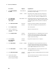
As shown in Table 3-3 and Figure 3-8, the FLT/INH connector can also be configured as a digital I/O
port. Information on programming the digital I/O port is found in chapter 5 and under
[SOURce:]DIGital:DATA and [SOURce:]DIGital:FUNCtion commands in chapter 8. The electrical
characteristics of the digital connector are described in appendix A.
Table 3-3. FLT/INH DIGital I/O Connector
PIN FAULT/INHIBIT DIGITAL I/O
1 FLT Output Output 0
2 FLT Common Output 1
3 INH Input Input/Output 2
4 INH Common Common
B) Digital Interface Circuits
A) Relay Circuits
INH FLT
. . . .
NOTE: Connectors
are removable
+ - +
Digital Input
Port 2
Relay Driver
Ports 0, 1, 2
(contains internal
clamp diodes for
inductive flyback)
Digital Output
Ports 0, 1, 2
TTL, AS, CMOS, HC
+16.5V Max.
Coil Current
0.25A Max.
4 3 2 1
Figure 3-8. Digital I/O Examples