
User`s guide


Installation - 3
35
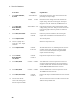
Figure 3-6. Local Sensing
OVP Considerations
CAUTION: Disabling the OVP protection circuit may cause excessive output voltages, such as can
occur if remote sense leads are shorted, to damage the equipment under test.
The dc source is shipped from the factory with its overvoltage protection circuit enabled. You can disable
the OVP circuit using either the front panel VOLT PROT command located in the OV menu, or the
VOLTage:PROTection:STATe SCPI command as explained in chapter 8.
The OVP circuit contains a crowbar SCR, which effectively shorts the output of the dc source whenever
the OVP trips. However, if an external current source such as a battery is connected across the output and
the OVP is inadvertently triggered, the SCR will continuously sink a large current from the battery,
possibly damaging the dc source.
To avoid this, either disable the OVP circuit or program it to its maximum value to prevent it from
inadvertently tripping. Additionally, you can connect an external protection diode in series with the
output of the dc source. Connect the anode of the diode to the + output terminal.
The OVP circuit's SCR crowbar has also been designed to discharge capacitances up to a specific limit,
which is 50,000 µF. If your load capacitance approaches this limit, it is recommended that you do not
intentionally trip the OVP and discharge the capacitance through the SCR as part of your normal testing
procedure, as this may lead to long-term failure of some components.
Local
Remote
SENSE
LOAD
SENSE
SWITCH IN
HP 66311A OUTPUT
CONNECTOR
+
_
-S - + +S
TWIST LEADS
WIRE RESISTANCE
EACH LEAD MUST
BE LESS THAN 20
INCHES IN LENGTH