
User`s guide


3 - Installation
32
The overvoltage protection circuit senses voltage near the output terminals, not at the load. Therefore the
signal sensed by the OVP circuit can be significantly higher than the actual voltage at the load. When
using remote sensing, you must program the OVP trip voltage high enough to compensate for the voltage
drop between the output terminals and the load. Also, if the sum of the programmed voltage and the load-
lead drop exceeds the maximum voltage rating of the dc source, this may also trip the OV protection
circuit. Refer to OVP considerations for more information.
Maintaining Stability while Remote Sensing
The remote sense bandwidth and slew rate of standard dc power sources are adequate for compensating
for load lead voltage drop for slow to moderate rates of load changes. However, the high pulsed current
draw of digital cellular phones presents a challenge to standard dc power sources operating in remote
sense mode. Their bandwidth and slew rate are not adequate for dealing with the 0.05 to 0.2 amp/µs slew
rates imposed by these devices. A large voltage transient occurs at the load, due to the inability of the dc
source to keep up with the rate of load change.
In remote sense mode, the Agilent 66111A/66311B effectively compensates for load lead voltage drops
resulting from very high slew rate load current transitions and thus keeps the remotely sensed output
voltage at a constant level. For 0.05 amp/µs to 0.2 amp/µs slew rate loading in typical test applications,
the transient voltage is reduced more than an order of magnitude over that of a standard dc source.
Open Sense Lead Protection
The dc source has built-in open sense protection circuitry that detects if a remote sense lead has opened.
For battery powered devices, undetected open sense connections can cause incorrect battery charger
calibration, incorrect test results due to erroneous voltage settings, and low voltage phone shutdown due
to a large transient voltage drop.
If the open sense lead protection circuit detects a resistance greater than 100K ohms in the sense leads,
the Prot annunciator on the front panel turns on and the output turns off. Bit 5 in the Questionable
Status Registers is also set (see chapter 7 under "Programming the Status Registers"). On the front panel,
press the Prot key, and one of the following error messages will be reported on the front panel:
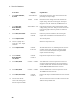
Message
Description
+ sense open
Positive sense lead is open
- sense open
Negative sense lead is open
+/- sense open
Both positive and negative sense leads are open
sense open
Incorrect resistance reading on the sense leads
This may be caused by an external power source paralleled with the output, or in
rare instances, by the voltage being out of calibration.
The sense leads are checked every time the output state transitions from disabled to enabled. This can be
done using the Output On/Off key or the Output On command. If a sense lead opens while the output is
enabled, this will not be detected by the open sense circuit until the output transitions from disabled to
enabled. Meanwhile, the output voltage will either increase or decrease, depending on which one of the
sense leads is open. Figure 3-5 illustrates the actual output voltage change that occurs with zero output
current if a sense lead opens. Turning the output Off, then On, when this occurs will cause the unit to
check the sense leads and determine if a sense lead is indeed open.