
User`s guide


Installation - 3
31
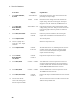
Figure 3-3. Remote Sense Connections with External Relays
Figure 3-4 shows how to connect remote sense leads when using a removable test fixture. Note that in
this configuration, the wires in the part of the test fixture where the phone is located must be less than 20
inches in length. This is for stability as well as for the fact that the remote sense leads cannot compensate
for the voltage drop in this part of the test fixture.
Figure 3-4. Remote Sense Connections with Test Fixture
Local
Remote
SENSE
LOAD
SENSE
SWITCH OUT
HP 66311A OUTPUT
CONNECTOR
+
_
-S - + +S
TWIST LEADS
WIRE RESISTANCE
TWIST PAIR
DISCONNECT RELAYS
Local
Remote
SENSE
LOAD
SENSE
SWITCH OUT
HP 66311A OUTPUT
CONNECTOR
+
_
-S - + +S
TWIST LEADS
WIRE RESISTANCE
LENGTH
MUST BE
UNDER 20
INCHES
TWIST PAIR
FIXTURE
CONNECTIONS
TWIST LEADS