
User`s guide


Verification and Calibration - B
139
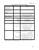
Check the Language Setting
The verification procedures can only be performed with the dc source set to the SCPI programming
language.
Action Normal Result
1. Turn on the dc source, access the Address menu and scroll to the
LANG: command.
LANG: SCPI or
LANG:COMP
2. If the language is set to COMPatibility, change it to SCPI and press
Enter. If the language is already set to SCPI, just continue with the
verification procedure.
LANG: SCPI
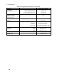
Voltage Programming and Measurement Accuracy
This test verifies the voltage programming, GPIB measurement, and front panel meter functions. Values
read back over the GPIB should be the same as those displayed on the front panel. Measure the dc output
voltage at the output terminals. Make sure the sense switch is set to remote and the sense terminals are
directly jumpered to the output terminals.
Action Normal Result
1. Turn off the dc source and connect a DMM to the output terminals.
2. Turn on the dc source with no load on the output. Set the output
voltage to 0.01 V and the output current to 3 A. Press Output
On/Off to enable the output.
Output voltage near 0 V.
Output current near 0 A.
3. Record the voltage reading on the DMM (Vout) and the voltage
reading on the front panel display.
Readings within low voltage limits
(see table B-2).
4. Set the output voltage to 15 V. Output voltage near 15 V.
5. Record the voltage reading on the DMM (Vout) and the voltage
reading on the front panel display.
Readings within high voltage limits
(see table B-2).
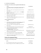
Current Programming and Measurement Accuracy
This test verifies the current programming and measurement. Connect the appropriate current monitor
(see table B-1) as shown in figure B-1A.
High Range Current Programming and Measurement
Action Normal Result
1. Turn off the dc source and connect the DMM and current monitor
as shown in figure B-1A. Then turn on the dc source.
2.
Agilent Model 66311B Only
Access the Input menu, and set the current sense detector to DC.
CURR:DET DC
3.
Set the output voltage to 5 V and the current to 0 A. Press Output
On/Off to enable the output.
Output current near 0 A.
4. Divide the voltage drop across the current monitor by its resistance
to convert the value to amperes. Record this value (Iout).
Reading within low current limits
(see table B-2).
5. Set the output current 3 A.
6. Divide the voltage drop across the current monitor by its resistance
to convert the value to amperes. Record this value (Iout). Also
record the current reading on the front panel display.
Readings within high current limits
(see table B-2).