
User`s guide


B - Verification and Calibration
138
Load
-S
-
+
+S
Local
Remote
SENSE
+
-
50VDC MAX TO
NOTE: Connector
is removable
Resistor
DC
Ammeter
-
+
Load
-S
-
+
+S
Local
Remote
SENSE
+
-
50VDC MAX TO
NOTE: Connector
is removable
resistor
DC
Ammeter
-
+
+
-
External
Set to
Remote
Set to
Remote
DC supply
A
.
B.
C.
-S
-+
+S
Local
Remote
SENSE
+
-
50VDC MAX TO
NOTE: Connector
is removable
Set to
DC
Current
monitor
Voltmeter
Remote
-
+
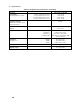
400 ohm
Calibration Load Resistor
800 ohms
Verification Load Resistor
400 ohms
Current Shunt
15 A, 0.10 ohms
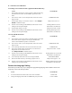
Figure B-1. Verification and Calibration Test Setup
Performing the Verification Tests
The following procedures assume you understand how to operate the dc source from the front panel as
explained in chapter 5. Also, when performing the verification tests from an GPIB controller, you may
have to consider the relatively slow settling times and slew rates of the dc source as compared to
computer and system voltmeters. Suitable WAIT statements can be inserted into the test program to give
the dc source time to respond to the test commands.
Perform the following tests for operation verification in the order indicated.
1. Turn-On Checkout
2. Voltage Programming and Measurement Accuracy
3. Current Programming and Measurement Accuracy
Turn-On Checkout
NOTE: The dc source must pass turn-on selftest before you can proceed with the verification
tests.
Perform the Turn-On Checkout as directed in chapter 4.