
User`s guide


N675xA:
The automatic setting adjust-
ment done in the 662xA when
the range changes will not occur
because it is no longer necessary
due to the autoranging capabil-
ity of the N675xA. Since there
is no range switching, the
“coupled parameter” (CP) bit
is never set.
Range Programming
25 W and 50 W
Precision Outputs:
The range can be set by using
the “VRSET” or “IRSET” com-
mands. The power supply will
automatically pick the range
that the value sent fits into. If
the value sent requires a range
change (high to low or low to
high) the “coupled parameter”
(CP) bit is set.
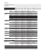
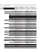
N676xA 50 W Precision
Output Module:
The functionality is the same
as above, but the ranges are
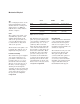
different. Table 6 below shows
the ranges for the different
outputs.
Functions that operate
differently or are missing
For compatibility, most
commands from the 662xA
language are accepted, however,
some commands do nothing.
Commands that “do nothing”
are accepted and do not pro-
duce an error, but no function
is performed. The commands
that are not accepted will
return “Error 203, Compatibility
function not implemented”.
ID? Query
The “ID?” query, when sent to
the N6700A will always return
“N6700A”.
OCRST and OVRST
662xA: “OCRST <ch>” returns
the specified channel to the
settings it had prior to being
turned off by the overcurrent
protection circuit, clearing
ONLY the OC condition.
“OVRST <ch>” attempts to reset
the overvoltage crowbar circuit
in the specified output channel,
clearing only the OV condition.
N6700A: Both OVRST and
OCRST will reset ALL latched
protection functions for the
specified channel.
Calibration
None of the 662xA calibration
commands are provided in the
compatibility language of the
N67xxA. Calibration must be
done exclusively in the SCPI
language format. Use of any
of the 662xA’s calibration
command set will result in an
error message. Please refer
to Calibration in the N67xxA
User’s Guide for the calibration
procedure.
Multiple Output Storage & Recall
6621A, 6622A, 6623A,
6624A, 6627A:
These models have 10 internal
registers, which have the
following characteristics:
• All registers (1-10) can store
the voltage (VSET) and
current (ISET) settings for
all the outputs.
• When a register is recalled
“RCL <reg>”, the outputs are
set sequentially (1,2,3,4).
• At power-on, all registers
(1-10), because they are all
volatile, are reset to zero
volts and minimum current.
12
Range 25 W Precision 50 W Precision N6761A N6762A
High 0-50 V/0-500 mA 0-50 V/0-2 A 0-50 V/0-1.5 A 0-50 V/0-3 A
Low 0-7 V/0-15 mA 0-16 V/0-200 mA 0-5.5 V/0-100 mA 0-5.5 V/0-100 mA
Table 6. Output/Measurement Ranges