
Specifications


10
Characterize Inrush Current with an AC
Power Source/Analyzer
• Uncover component stresses
• Check to see if a product produces
ac mains disturbances that inter-
act with other products connected
to the same branch circuit
• Select proper fuses and circuit
breakers
However, this can be a challenging
measurement because you have to
synchronize the current digitization
and peak current measurement with
the startup phase of the voltage.
Worst case inrush currents occur
near the voltage cycle’s peak and
when the ac input capacitor of the
DUT is fully discharged at startup.
Therefore, you must perform tests at
incremental voltage startup phases
from around 40° to 90° (Figure 1)
and let the DUT’s ac input capacitor
discharge between tests.
A traditional test setup includes an
ac source with programmable phase
capability and an output trigger port,
a digital oscilloscope, and a current
probe. However, using an advanced
ac power source/analyzer such as the
Agilent 6800 series ac power
source/analyzers is easier because
they have built-in generation, current
waveform digitization, peak current
measurement, and synchronization
capabilities that let you perform
inrush current characterization with-
out cabling and synchronizing sepa-
rate instruments.
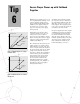
Figure 1: An inrush current measurement at 40° using Agilent 6800 series ac power
source/analyzers
Tip
9
Output
Voltage
Start up
phase of
40 degrees
Bus Trigger
Peak Current Measurement
Inrush Current
Digitized Inrush
Current
Data Points
The inrush current characteristics of
ac-dc switch mode power supplies
vary with the turn-on phase of the
voltage cycle. Usually, these power
supplies have input capacitors that
draw high peaks of inrush current as
they charge from the rectified ac line
at turn-on. Characterizing inrush cur-
rent versus turn-on phase can pro-
vide some important design insights: