
User`s guide

53
B
Verification and Calibration
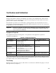
Introduction
This appendix includes verification and calibration procedures for the Agilent 66312A, 6611C, 6612C,
6613C and 6614C dc source. Instructions are given for performing the procedures either from the front
panel or from a controller over the GPIB.
The verification procedures do not check all the operating parameters, but verify that the dc source is
performing properly. Performance Tests, which check all the specifications of the dc source, are given in
the applicable dc source Service Manual.
Important Perform the verification procedures before calibrating your dc source. If the dc source
passes the verification procedures, the unit is operating within its calibration limits and
does not need to be recalibrated.
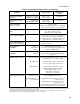
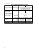
Equipment Required
The equipment listed in the following table, or the equivalent to this equipment, is required for
verification and calibration.
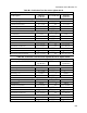
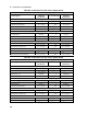
Table B-1. Equipment Required
Equipment Characteristics Recommended Model
Digital Voltmeter
Resolution: 10 nV @ 1 V
Readout: 8.5 digits
Accuracy: >20 ppm
Agilent 3458A
Current Monitor
1
15 A (0.1
Ω
),
±
0.04%, TC=5ppm/
°
C
Guildline 9230/15
Load Resistor
(3 W min. TC=20ppm/°C)
400
Ω
(Agilent 6611C calibration and all
models verification.)
1.1 k
Ω
(Agilent 6612C & 66312A calibration)
2500
Ω
(Agilent 6613C calibration)
5000
Ω
(Agilent 6614C calibration)
p/n 0811-2878
Power Supply
8 V @ 5 A Agilent 6611C or Agilent 6631B
GPIB Controller
Full GPIB capabilities HP Series 200/300 or equivalent
1
The 4- terminal current shunt is used to eliminate output current measurement error caused by voltage drops in the
load leads and connections. It has special current-monitoring terminals inside the load connection terminals. Connect
the voltmeter directly to these current-monitoring terminals.
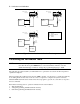
Test Setup
Figure B-1 shows the setup for the tests. Be certain to use load leads of sufficient wire gauge to carry the
full output current (see chapter 3).