
User`s guide


Installation - 3
29
♦ The total number of devices including the controller is no more than 15.
♦ The total length of all cables used is no more than 2 meters times the number of devices connected
together, up to a maximum of 20 meters. (Refer to table 2-2 for a list of GPIB cables available from
Agilent Technologies.)
♦ Do not stack more than three connector blocks together on any GPIB connector.
♦ Make sure all connectors are fully seated and the lock screws are firmly finger-tightened.
RS-232 Interface
The dc source has an RS-232 programming interface, which is activated by commands located in the
front panel
Address menu. All SCPI and COMPatibility commands are available through RS-232
programming. When the RS-232 interface is selected, the GPIB interface is disabled.
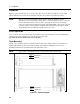
The RS-232 connector is a DB-9, male connector. Adapters are available to connect the dc source to any
computer or terminal with a properly configured DB-25 connector (see Table 2-2).
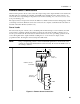
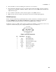
1 2 3 4 5
6 7 8 9
Figure 3-6. RS-232 Connector
Pin Input/Output Description
1 - no connection
2 Input Receive Data (RxD)
3 Output Transmit Data (TxD)
4 Output Data Terminal Ready (DTR)
5 Common Signal ground
6 Input Data Set Ready (DSR)
7 Output Request to Send (RQS)
8 Input Clear to Send (CTS)
9 - no connection