
User`s guide


3 - Installation
28
Digital I/O Connections
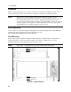
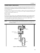
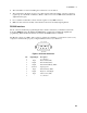
As shown in Table 3-3 and Figure 3-5, the FLT/INH connector can also be configured as a digital I/O
port. Information on programming the digital I/O port is found in chapter 5 and under
[SOURce:]DIGital:DATA and [SOURce:]DIGital: FUNCtion commands in the Programming Guide.
The electrical characteristics of the digital connector are described in appendix A.
Table 3-3. FLT/INH DIGital I/O Connector
PIN FAULT/INHIBIT DIGITAL I/O
1 FLT Output Output 0
2 FLT Common Output 1
3 INH Input Input/Output 2
4 INH Common Common
B) Digital Interface Circuits
A
)
Rela
y
Circuits
INH FLT
. . . .
NOTE: Connectors
are removable
+ - +
Di
g
ital Input
Port 2
Rela
y
Driver
Ports 0
,
1
,
2
(
contains internal
clamp diodes for
inductive fl
y
back
)
Digital Output
Ports 0, 1, 2
TTL
,
AS
,
CMOS
,
HC
+16.5V Max.
Coil Current
0.25A Max.
4321
Figure 3-5. Digital I/O Examples
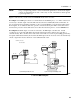
Controller Connections
The dc source connects to a controller either through an GPIB or an RS-232 connector.
GPIB Interface
Each dc source has its own GPIB bus address, which can be set using the front panel Address key as
described in chapter 5. GPIB address data is stored in non-volatile memory. The dc source is shipped
with its GPIB address set to 5.
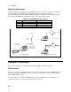
Dc sources may be connected to the GPIB interface in series configuration, star configuration, or a
combination of the two, provided the following rules are observed: