
User`s guide


Installation - 3
27
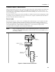
NOTE: It is good engineering practice to twist and shield all signal wires to and from the digital
connectors. If shielded wire is used, connect only one end of the shield to chassis ground
to prevent ground loops.
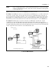
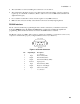
Figure 3-4 shows how you can connect the FLT/INH circuits of the dc source.
In example A, the INH input connects to a switch that shorts the Inhibit pin (+) to common whenever it
is necessary to disable output of the unit. This activates the remote inhibit (RI) circuit, which turns off
the dc output. The front panel Prot annunciator comes on and the RI bit is set in the Questionable Status
Event register. To re-enable the unit, first open the connection between pins INH + and common and
then clear the protection circuit. This can be done either from the front panel or over the GPIB/RS-232.
In example B, the FLT output of one unit is connected to the INH input of another unit. A fault
condition in one of the units will disable all of them without intervention either by the controller or
external circuitry. The controller can be made aware of the fault via a service request (SRQ) generated by
the Questionable Status summary bit. Note that the FLT output can also be used to drive an external relay
circuit or signal other devices whenever a user-definable fault occurs.
FLT
Output
INH
Input
B) FLT Example with Multiple Units
FLT
Output
INH
Input
Switch
(Normally
Open)
INH Common
INH Input
A) INH Example with One Unit
INH FLT
. . . .
INH FLT
. . . .
NOTE: Connectors
are removable
+ - +
+ - +
4321
4321
4321
Figur
e 3-4. FLT/INH Examples