
User`s guide


3 - Installation
26
The overvoltage protection circuit senses voltage near the output terminals, not at the load. Therefore the
signal sensed by the OVP circuit can be significantly higher than the actual voltage at the load. When
using remote sensing, you must program the OVP trip voltage high enough to compensate for the voltage
drop between the output terminals and the load. Also, if the sum of the programmed voltage and the load-
lead drop exceeds the dc source’s maximum voltage rating, this may also trip the OV protection circuit.
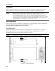
Stability
When the unit is configured for remote sensing, it is possible for the impedance of the load wires and the
capacitance of the load to form a filter, which becomes part of the unit’s feedback loop. This can degrade
the unit’s stability and result in poor transient response performance. In extreme cases it may also cause
oscillations. The wiring guidelines previously discussed under "Wire Considerations" will eliminate most
stability problems associated with load lead inductance. If additional measures are required:
♦ keep the load capacitance as small as possible
♦ use larger diameter load wires to reduce resistance
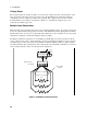
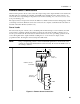
OVP Considerations
The dc source’s OVP circuit contains a crowbar SCR, which effectively shorts the output of the dc
source whenever the OVP trips. If an external voltage source such as a battery is connected across the
output and the OVP is inadvertently triggered, the SCR will continuously sink a large current from the
battery, possibly damaging the dc source.
To avoid this, program the OVP setting to its maximum value to prevent it from inadvertently tripping.
Additionally, an internal fuse is connected in series with the SCR. This fuse will open to prevent large
currents from damaging the SCR. If this internal fuse has opened, The FS status annunciator will be set.
Refer to the Service Manual for instructions about replacing this fuse.
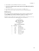
In addition, the OVP circuit’s SCR crowbar has been designed to discharge capacitances up to a specific
limit. This limit is:
Agilent 6611C
127,000 µF.
Agilent 6613C
20,000 µF.
Agilent 6612C and 66312A
50,000 µF.
Agilent 6614C
10,000 µF.
If your load capacitance approaches this limit, it is recommended that you do not intentionally trip the
OVP and discharge the capacitance through the SCR as part of your normal testing procedure, as this
may lead to long-term failure of some components.
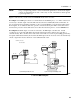
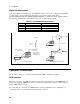
INH/FLT Connections
This rear panel connector, has a fault output port and an inhibit input port. The fault (FLT) output, also
referred to as the DFI (discrete fault indicator) signal in the front panel and SCPI commands, is an open
collector circuit that pulls the positive output low with respect to the negative (chassis-referenced)
common. The high impedance inhibit (INH) input, also referred to as the RI (remote inhibit) signal in the
front panel and SCPI commands, is used to shut down the power supply output whenever the INH + is
pulled low with respect to the INH (chassis-referenced) common.
The connector accepts wires sizes from AWG 22 to AWG 12. Disconnect the mating plug to make your
wire connections.