USER’S GUIDE Dynamic Measurement DC Source Agilent Model 66312A System DC Power Supply Agilent 6611C, 6612C, 6613C and 6614C s1 Agilent Part No. 5962-8194 Microfiche No.
Warranty Information CERTIFICATION Agilent Technologies certifies that this product met its published specifications at time of shipment from the factory. Agilent Technologies further certifies that its calibration measurements are traceable to the United States National Bureau of Standards, to the extent allowed by the Bureau’s calibration facility, and to the calibration facilities of other International Standards Organization members.
Safety Summary The following general safety precautions must be observed during all phases of operation of this instrument. Failure to comply with these precautions or with specific warnings elsewhere in this manual violates safety standards of design, manufacture, and intended use of the instrument. Agilent Technologies assumes no liability for the customer's failure to comply with these requirements. GENERAL This product is a Safety Class 1 instrument (provided with a protective earth terminal).
SAFETY SYMBOLS Direct current Alternating current Both direct and alternating current Three-phase alternating current Earth (ground) terminal Protective earth (ground) terminal Frame or chassis terminal Terminal is at earth potential. Used for measurement and control circuits designed to be operated with one terminal at earth potential.
Declaration Page DECLARATION OF CONFORMITY according to ISO/IEC Guide 22 and EN 45014 Manufacturer’s Name: Agilent Technologies Manufacturer’s Address: 140 Green Pond Road Rockaway, New Jersey 07866 U.S.A.
Acoustic Noise Information Herstellerbescheinigung Diese Information steht im Zusammenhang mit den Anforderungen der Maschinenläminformationsverordnung vom 18 Januar 1991. * Schalldruckpegel Lp <70 dB(A) * Am Arbeitsplatz * Normaler Betrieb * Nach EN 27779 (Typprüfung). Manufacturer’s Declaration This statement is provided to comply with the requirements of the German Sound Emission Directive, from 18 January 1991.
Table of Contents Warranty Information Safety Summary Declaration Page Acoustic Noise Information Printing History Table of Contents 2 3 5 6 6 7 1 - QUICK REFERENCE 9 Agilent 66312A Dynamic Measurement DC Source and Agilent 6611C/6612C/6613C/6614C System DC Power Supply The Front Panel - At a Glance Front Panel Number Entry Front Panel Annunciators Immediate Action Keys Front Panel Menus - At a Glance SCPI Programming Commands - At a Glance The Rear Panel - At a Glance 2 - GENERAL INFORMATION Document
4 - TURN-ON CHECKOUT Introduction Using the Keypad Checkout Procedure In Case of Trouble Error Messages Line Fuse 5 - FRONT PANEL OPERATION Introduction Front Panel Description System Keys Function Keys Immediate Action Keys Scrolling Keys Metering Keys Output Control Keys Entry Keys Examples of Front Panel Programming 1 - Setting the Output Voltage and Current 2 - Querying and Clearing Output Protection 3 - Making Front Panel Measurements 4 - Programming the Digital Output Port 5 - Programming the Output
1 Quick Reference Agilent 66312A Dynamic Measurement DC Source and Agilent 6611C/6612C/6613C/6614C System DC Power Supply The Agilent 66312A is a 40 Watt, high performance dc power supply that provides dynamic measurement and analysis of voltage and current waveforms. It is designed to simplify the testing of digital cellular and mobile phones.
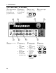
1 - Quick Reference The Front Panel - At a Glance j 14-character display shows output measurements and programmed values. k l Annunciators indicate operating modes and status conditions. 1 Rotary control sets voltage, current, and menu parameters. m Front panel output connectors. Use É and Ê to set the resolution; then adjust the value with the knob.
Quick Reference - 1 Front Panel Number Entry Enter numbers from the front panel using one of the following methods: Use the arrow keys and knob to change voltage or current settings NOTE The output must be ON to see the displayed values change in Meter mode.
1 - Quick Reference Front Panel Annunciators CV The output is operating in constant voltage mode. CC The output is operating in constant current mode. Unr The output is unregulated. Dis The output is OFF. Press the Output On/Off key to turn the output on. OCP The over-current protection state is ON. Press the OCP key to turn over-current protection off. Prot Indicates that the output has been disabled by one of the protection features. Press the Prot Clear key to clear the protection condition.
Quick Reference - 1 Front Panel Menus - At a Glance Address ô ô ô ô ô Recall ADDRESS 7 Sets the GPIB Address INTF GPIB Selects an interface (GPIB or RS232) BAUDRATE 300 Selects baud rate (300, 600, 1200, 2400, 4800, 9600) PARITY NONE Selects message parity (NONE, EVEN, ODD, MARK, SPACE) FLOW NONE Selects flow control (XON-XOFF, RTS-CTS, DTR-DSR, NONE) LANG SCPI Selects language (SCPI or COMP) *RCL 0 Recalls instrument state Shift Save *SAV 0 Saves present instrument state Shift Error
1 - Quick Reference SCPI Programming Commands - At a Glance NOTE Most [optional] commands have been omitted for clarity. Refer to the Programming Guide for a complete description of all programming commands.
Quick Reference - 1 The Rear Panel - At a Glance j GPIB (IEEE-488) interface connector k RS-232 interface connector l 2 1 nRemote or Local sense switch m INH/FLT (remote INHibit / internal FauLT) connector. Connector plug is removable. 4 5 oFuse holder pPower cord Output and Remote sense connector. Connector plug is removable.
2 General Information Document Orientation This manual describes the operation of the Agilent Model 66312A Dynamic Measurement DC Source and the Agilent Model 6611C, 6612C 6613C and 6614C System DC Power Supplies. Unless otherwise noted, all units will be referred to by the description "dc source" throughout this manual.
2 - General Information Safety Considerations This dc source is a Safety Class 1 instrument, which means it has a protective earth terminal. That terminal must be connected to earth ground through a power source equipped with a ground receptacle. Refer to the Safety Summary page at the beginning of this guide for general safety information. Before installation or operation, check the dc source and review this guide for safety warnings and instructions.
General Information - 2 Description Both the Agilent 66312A Dynamic Measurement DC Source and the Agilent 6611C, 6612C, 6613C and 6614C System DC Power Supplies combine two instruments in one unit. They include a dc source, which produces dc output with programmable voltage and current amplitude, and a highly accurate voltage and current meter, with the capability to measure very low-level currents.
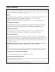
2 - General Information Output Characteristic The dc source’s output characteristic is shown in the following figure. The output of the dc source may be adjusted to any value within the boundaries shown. Output Voltage CV operating line Vmax VSET 1 2 CC operating line - + -Isink (60% Imax) 0 ISET Output Current Imax Figure 2-1. Dc Source Output Characteristic The dc source can operate in either constant voltage (CV) or constant current (CC) over the rated output voltage and current.
3 Installation Inspection Damage When you receive your dc source, inspect it for any obvious damage that may have occurred during shipment. If there is damage, notify the shipping carrier and the nearest Agilent Sales and Support Office immediately. The list of Agilent Sales and Support Offices is at the back of this guide. Warranty information is printed in the front of this guide.
3 - Installation Location Figure 3-1 gives the dimensions of your dc source. The dc source must be installed in a location that allows sufficient space at the sides and back for adequate air circulation (see Bench Operation). NOTE: This dc source generates magnetic fields that may affect the operation of other instruments. If your instrument is susceptible to operating magnetic fields, do not locate it in the immediate vicinity of the dc source.
Installation - 3 Input Connections Connect the Power Cord 1. Unscrew the line fuse cap from the rear panel and verify that the fuse rating matches what is specified on the FUSES label on the rear panel. Reinstall the fuse. (See table 3-1 for fuse part numbers.) 2. Connect the power cord to the IEC 320 connector on the rear of the unit.
3 - Installation Voltage Drops The load wires must also be large enough to avoid excessive voltage drops due to the impedance of the wires. In general, if the wires are heavy enough to carry the maximum short circuit current without overheating, excessive voltage drops will not be a problem. The voltage drops across the load wires should be limited to less than two volts. Refer to Table 3-2 to calculate the voltage drop for some commonly used AWG copper wire.
Installation - 3 Remote Sense Connections Under normal operation, the dc source senses the output voltage at the output terminals on the back of the unit. External sense terminals are available on the back of the unit that allow the output voltages to be sensed at the load, compensating for impedance losses in the load wiring. You cannot remote sense at the front panel binding posts. The output connector accepts wires sizes from AWG 22 to AWG 12. Disconnect the mating plug to make your wiring connections.
3 - Installation The overvoltage protection circuit senses voltage near the output terminals, not at the load. Therefore the signal sensed by the OVP circuit can be significantly higher than the actual voltage at the load. When using remote sensing, you must program the OVP trip voltage high enough to compensate for the voltage drop between the output terminals and the load.
Installation - 3 NOTE: It is good engineering practice to twist and shield all signal wires to and from the digital connectors. If shielded wire is used, connect only one end of the shield to chassis ground to prevent ground loops. Figure 3-4 shows how you can connect the FLT/INH circuits of the dc source. In example A, the INH input connects to a switch that shorts the Inhibit pin (+) to common whenever it is necessary to disable output of the unit.
3 - Installation Digital I/O Connections As shown in Table 3-3 and Figure 3-5, the FLT/INH connector can also be configured as a digital I/O port. Information on programming the digital I/O port is found in chapter 5 and under [SOURce:]DIGital:DATA and [SOURce:]DIGital: FUNCtion commands in the Programming Guide. The electrical characteristics of the digital connector are described in appendix A. Table 3-3.
Installation - 3 ♦ The total number of devices including the controller is no more than 15. ♦ The total length of all cables used is no more than 2 meters times the number of devices connected together, up to a maximum of 20 meters. (Refer to table 2-2 for a list of GPIB cables available from Agilent Technologies.) ♦ Do not stack more than three connector blocks together on any GPIB connector. ♦ Make sure all connectors are fully seated and the lock screws are firmly finger-tightened.
4 Turn-On Checkout Introduction Successful tests in this chapter provide a high degree of confidence that the dc source is operating properly. For verification tests, see appendix B. Complete performance tests are given in the Service Guide. NOTE: This chapter provides a preliminary introduction to the dc source front panel. See chapter 5 for more details. Using the Keypad (shift) Some of the front panel keys perform two functions, one labeled in black and the other in blue.
4 - Turn-On Checkout Checkout Procedure The tests in this section checks for output voltage and current on the dc source. NOTE: To perform the checkout procedure, you will need a wire for shorting the output terminals together. The following procedure assumes that the unit turns on in the factory-default state. If you need more information about the factory default state, refer to the *RST command in chapter 4 of the Programming Guide.
Turn-On Checkout - 4 Procedure 6. Press Enter Number, 8, Enter Display VOLT:PROT 8 0.449V 0.145A Explanation Programs the OVP to 8 volts, which is less than the previously set output voltage. Because the OVP voltage entered was less than the output voltage, the OVP circuit tripped. The output dropped to zero, CV turned off, and Prot turned on. 7. Press Shift, OV, Enter Number, <2, 2>, Enter 8. Press Shift, Prot Clear 9. Press Output on/off Turn the output off. 10.
4 - Turn-On Checkout In Case of Trouble Error Messages Dc source failure may occur during power-on selftest or during operation. In either case, the display may show an error message that indicates the reason for the failure. Selftest Errors Pressing the Shift, Error keys will show the error number. Selftest error messages appear as: ERROR where "n" is a number listed in the following table. If this occurs, turn the power off and then back on to see if the error persists.
5 Front panel Operation Introduction Here is what you will find in this chapter: ♦ a complete description of the front panel controls ♦ front panel programming examples NOTE: The dc source must be in set to Local mode to use the front panel controls. Press the Local key on the front panel to put the unit in local mode.
5 - Front Panel Operation j Display 14-character vacuum fluorescent display for showing output measurements and programmed values. k Annunciators Annunciators light to indicate operating modes and status conditions: CV The dc source output is in constant-voltage mode. CC The dc source output is in constant-current mode. Unr The dc source output is in an unregulated state. Dis The dc source output is disabled (off). OCP The overcurrent protection state is enabled.
Front Panel Operation - 5 System Keys Refer to the examples later in this chapter for more details on the use of these keys. SYSTEM Error Local Address Save Recall Figure 5-2. System Keys This is the blue, unlabeled key, which is also shown as Shift in this guide. Pressing this key accesses the alternate or shifted function of a key (such as ERROR ). Release the key after you press it. The Shift annunciator is lit, indicating that the shifted keys are active.
5 - Front Panel Operation Function Keys Refer to the examples later in this chapter for more details on the use of these keys. FUNCTION Input OV Meter Voltage Output Prot Cir OCP Cal Protect Current Output On/Off Figure 5-3. Function Keys Immediate Action Keys Immediate action keys immediately execute their corresponding function when pressed. Other function keys have commands underneath them that are accessed when the key is pressed.
Front Panel Operation - 5 Metering Keys Metering keys control the metering functions of the dc source. When the unit is operating in front panel meter mode, all front panel measurements are calculated from a total of 2048 readings taken at a 46.8 microsecond sampling rate. Therefore, the total acquisition time for a single front panel measurement is about 100 milliseconds. Refer to “Making Front Panel Measurements” for more information.
5 - Front Panel Operation Output Control Keys Output control keys control the output functions of the dc source. Voltage Press this key to access the voltage menu. Display Command Function VOLT Current Sets the output voltage Press this key to access the current menu. Display Command Function CURR Output Sets the output current Press this key to access the output menu list.
Front Panel Operation - 5 Entry Keys Refer to the examples later in this chapter for more details on the use of these keys. ENTRY Cir Entry 1 2 3 4 5 . 6 7 8 9 0 - Enter Number Enter Backspace Ë Ì É Ê Enter Number 0 . , Figure 5-4. Entry Keys These keys let you scroll through choices in a parameter list that apply to a specific command. Parameter lists are circular; you can return to the starting position by continuously pressing either key.
5 - Front Panel Operation Examples of Front Panel Programming You will find these examples on the following pages: 1 Setting the output voltage and current 2 Querying and clearing output protection 3 Making front panel measurements 4 Programming the digital port 5 Programming the output relay (option 760 only) 6 Setting the GPIB address or RS-232 parameters 7 Saving and recalling operating states Similar examples are given in the dc source Programming Guide using SCPI commands.
Front Panel Operation - 5 2 - Querying and Clearing Output Protection The dc source will disable its output if it detects an overvoltage or overcurrent fault condition. Other automatic fault conditions (such as overtemperature) also will disable the output. Query and clear the dc source overcurrent protection feature as follows: Action Display 1. On the Function keypad, press Protect. In this example, OC indicates that an overcurrent condition has occurred.
5 - Front Panel Operation V or A MAX 46.8 microsecond sampling rate V or A HIGH NOTE: Measurement samples may not coincide with the actual maximum or minimum point of the waveform. V or A LOW V or A MIN 100 millisecond acquisition time Figure 5-5. Front Panel Pulse Measurement Parameters (Agilent 66312A only) Use the Meter menu for making front panel measurements: Action Display 1. For current measurements, press Shift, Input. Then press Ì until you obtain the CURR:RANG AUTO command.
Front Panel Operation - 5 Your dc source is shipped with the output port function set to RIDFI mode. In this mode the port functions as a remote inhibit input with a discrete fault indicator output signal. You can also configure the port to act as a Digital Input/Output device. To configure the RIDFI mode of the port, proceed as follows: Action Display 1. On the Function keypad, press Output. *RST 2. Scroll through the Output menu by pressing q .
5 - Front Panel Operation 5 - Programming the Output Relay (option 760 only) Units with option 760 have isolation and polarity reversal relays connected to the output and sense terminals. (Option 760 is not available on Agilent 66312A units.) To control the relays independently of the Output On/Off switch, proceed as follows: Action Display 1. On the Function keypad, press Output, and scroll through the Output menu until you get to the RELAY command.
Front Panel Operation - 5 7 - Saving and Recalling Operating States NOTE: This capability is only available when the unit is set to the SCPI programming language. You can save up to 4 states (from location 0 to location 3) in non-volatile memory and recall them from the front panel. All programmable settings are saved. Save an operating state in location 1 as follows: Action 1. Set the instrument to the operating state that you want to save. 2. Save this state to location 1.
A Specifications Specifications Table A-1 lists the specifications of the dc source. Specifications are warranted over the ambient temperature range of 0 to 55 °C. Unless otherwise noted, specifications apply when measured at the rear terminals after a 30-minute warm-up period. Table A-1.
A - Specifications Supplemental Characteristics Table A-2 lists the supplemental characteristics, which are not warranted but are descriptions of typical performance determined either by design or type testing. Table A-2. Supplemental Characteristics Parameter Input Rating 47 – 63 Hz (at full load) Agilent 6611C Agilent6612C Agilent 66312A Agilent 6613C Agilent 6614C 2.2 A, 120 W 1.6 A, 100 W 1.6 A, 100 W 1.6 A, 100 W 115 Vac mains: (104-127 Vac) 2 A, 120 W 1.4 A, 100 W 1.4 A, 100 W 1.
Specifications - A Table A-2. Supplemental Characteristics (continued) Parameter Agilent 66312A Agilent 6611C 6614C Dynamic Measurement Accuracy Instantaneous Voltage: Instantaneous Current: 0.03% + 5 mV 0.6% + 1 mA1 not applicable Dynamic Measurement System Buffer Length: Sampling Rate Range: 4096 points 15.
A - Specifications Table A-2. Supplemental Characteristics (continued) Parameter Digital I/O Characteristics (continued) Agilent 66312A Digital IN Port 2: (internal pull-up) 240 Vdc 1 year (from the date the unit is put into service) Recommended Calibration Interval Regulatory Compliance Low-level input current @ 0.4 V = 1.25 mA High-level input current @ 5 V = 0.25 mA Low-level input voltage = 0.8 V max. High level input voltage = 2.0 V min.
B Verification and Calibration Introduction This appendix includes verification and calibration procedures for the Agilent 66312A, 6611C, 6612C, 6613C and 6614C dc source. Instructions are given for performing the procedures either from the front panel or from a controller over the GPIB. The verification procedures do not check all the operating parameters, but verify that the dc source is performing properly.
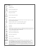
B - Verification and Calibration SENSE -S - + SENSE -S +S - + Local + - +S Local Remote NOTE: Connector is removable Remote NOTE: Connector is removable + - 50VDC MAX TO 50VDC MAX TO Set to Remote Set to Remote DC - DC Current Voltmeter - Load Resistor Ammeter monitor + + B. A. SENSE -S - + +S Local Remote NOTE: Connector is removable + 50VDC MAX TO Set to Remote DC - Calibration Load Resistor 400 6611C 1.1K 6612C & 66312A 2.
Verification and Calibration - B Table B-2. Verification Programming Values 6611C 6612C/66312A 6613C 6614C Full scale Voltage 8 20 50 100 Full Scale Current 5 2 1 0.5 Imax Isink 5.1188 2.0475 1.0238 0.5118 -3A - 1.2 A - 0.6 A - 0.3 A Turn-On Checkout Perform the Turn-On Checkout as directed in chapter 4. NOTE: The dc source must pass turn-on selftest before you can proceed with the verification tests.
B - Verification and Calibration to convert the value to amperes. Record the value. 5. Set the output current to full scale (see table B-2).. 6. Divide the voltage drop across the current monitor by its resistance to convert the value to amperes. Record this value and the current reading on the front panel display. limits (see table B-3, 4, 5 or 6). Readings within high current limits (see table B-3, 4, 5 or 6). Current Measurement (Low Range) Action 7.
Verification and Calibration - B Table B-3. Verification Test Record for Agilent 6611C Model Agilent 6611C Report No.____________ Test Description Minimum Specification Date_____________ Recorded Results Maximum Specification Voltage Programming and Measurement Low Voltage Vout Front Panel measurement High Voltage Vout Front Panel measurement −5 mV _______V +5 mV Vout −2 mV _____mV Vout +2 mV 7.991 V _______V 8.009 V Vout −4.4 mV _____mV Vout +4.
B - Verification and Calibration Table B-5. Verification Test Record for Agilent 6613C Model Agilent 6613C Report No.____________ Test Description Minimum Specification Date_____________ Recorded Results Maximum Specification Voltage Programming and Measurement Low Voltage Vout Front Panel measurement High Voltage Vout Front Panel measurement −20 mV _______V +20 mV Vout −6 mV _____mV Vout +6 mV 49.955 V _______V 20.
Verification and Calibration - B Performing the Calibration Procedure NOTE: The calibration procedure can only be performed using the SCPI language commands. Use either the front panel Address key to access the LANG command, or use the SYSTem:LANGuage command to change the programming language to SCPI. Table B-1 lists the equipment required for calibration. Figure B-1 shows the test setup. You do not have to do a complete calibration each time.
B - Verification and Calibration These procedures assume you understand how to operate front panel keys (see chapter 5). Enable Calibration Mode Action 1. Reset the unit by selecting Output, scrolling to *RST and pressing Enter. 2. Press Output On/Off to enable the output. 3. To begin calibration press Shift Cal, scroll to CAL ON and press Enter. 4. Enter the calibration password from Entry keypad and press Enter. lf the password is correct the Cal annunciator will come on.
Verification and Calibration - B Current Programming and High-Range Measurement Calibration Action Display 13. Connect the appropriate current monitor as shown in figure B-1A. Connect the DMM (in dc mode) across the current shunt. 14. Press Shift Cal, scroll to CAL CURR, and press Enter. CAL:CURR 15. Press Shift Cal, scroll to CAL LEV, and press Enter to select the first calibration point. CAL:LEV P1 16. Press Shift Cal and scroll to CAL DATA. Wait for the DMM reading to stabilize.
B - Verification and Calibration Saving the Calibration Constants WARNING: Storing calibration constants overwrites the existing ones in non-volatile memory. If you are not sure you want to permanently store the new constants, omit this step. The dc source calibration will then remain unchanged. Action Display 26. Press Shift Cal, scroll to CAL SAVE, and press Enter. CAL:SAVE 27. Press Shift Cal, select CAL OFF, and press Enter to exit Calibration mode.
Verification and Calibration - B Calibration Over the GPIB You can calibrate the dc source by using SCPI commands within your controller programming statements. Be sure you are familiar with calibration from the front panel before you calibrate from a controller. Each front panel calibration command has a corresponding SCPI command. When you write your calibration program, perform the calibration procedure in the same order as the front panel procedure documented in this appendix.
C Error Messages Error Number List This appendix gives the error numbers and descriptions that are returned by the dc source. Error numbers are returned in two ways: ♦ Error numbers are displayed on the front panel ♦ Error numbers and messages are read back with the SYSTem:ERRor? query. SYSTem:ERRor? returns the error number into a variable and returns two parameters: an NR1 and a string. The following table lists the errors that are associated with SCPI syntax errors and interface problems.
C - Error Messages –138 Suffix not allowed –141 Invalid character data [bad character, or unrecognized] –144 Character data too long –148 Character data not allowed –150 String data error –151 Invalid string data [e.g., END received before close quote] –158 String data not allowed –160 Block data error –161 Invalid block data [e.g.
Error Messages - C Selftest Errors 0 through 99 (sets Standard Event Status Register bit #3) 0 No error 1 Non-volatile RAM RD0 section checksum failed 2 Non-volatile RAM CONFIG section checksum failed 3 Non-volatile RAM CAL section checksum failed 4 Non-volatile RAM STATE section checksum failed 5 Non-volatile RST section checksum failed 10 RAM selftest 11 VDAC/IDAC selftest 1 12 VDAC/IDAC selftest 2 13 VDAC/IDAC selftest 3 14 VDAC/IDAC selftest 4 15 OVDAC selftest 80 Digital I/O s
D Line Voltage Conversion WARNING: Shock Hazard Operating personnel must not remove instrument covers. Component replacement and internal adjustments must be made only by qualified service personnel. Open the Unit ♦ Turn off ac power and disconnect the power cord from the unit. ♦ Loosen the two screws on the rear bezel and remove the bezel (use a #15 Torx drive). ♦ Remove the two screws on the bottom of the unit (use a #15 Torx drive). ♦ Pull the cover back to remove it from the unit.
D - Line Voltage Conversion Install the Correct Line Fuse ♦ Unscrew the line fuse cap from the rear panel and install the correct fuse. For 100/120 Vac operation: 2.5 AT (time delay); part number 2110-0633 For 220/230 Vac operation: 1.25 AT (time delay); part number 2110-0788 ♦ Mark the voltage setting that the unit has been set to on the rear panel label. Close the Unit ♦ Replace the outer cover. ♦ Reconnect the power cord and turn on the unit.
Index —— -- -- -- -- -- --, 43 —+— +/- terminals, 23 +S/-S terminals, 23 checkout procedure, 32 cleaning, 21 clear protection, 43 controller connections, 28 controls and indicators, 19 conversion, ac line, 69 crowbar circuit, 26 current measurement range, 43 CV mode, 20, 42 —D— —0— 0 ...
Index OCP, 38 Output, 40 Output On/Off, 38 OV, 40 Prot Clear, 38 Protect, 40 Voltage, 40 fuses, 23 —G— ground, earth, 18 guide, programming, 17 guide, user’s, 17 —H— history, 6 GPIB, 46 address, 46 connections, 28 interface, 28 operating features, 19 option 760, 46 options, 18 OT, 43 output characteristic, 20 connections, 23 connector, 21 control keys, 40 current setting, 42 enable, 42 rating, 20 voltage setting, 42 output relay, 46 OV, 43 OVLD, 34, 43 OVP capacitor discharge limit, 26 circuit, 26 —P— —
Index selftest errors, 34 sense connections, 25 service guide, 18 setting voltage/current, 42 shift annunciator, 31 shift key, 31 shorting switch, 27 specifications, 49 stability with remote sensing, 26 supplemental characteristics, 50 system errors, 65 system keys, 37 Address, 37 Error, 37 Interface, 37 Local, 37 RCL, 37 Save, 37 Shift, 37 —T— turn-on checkout, 31, 55 —V— verification current measurement accuracy, 55 current programming, 55 equipment, 53 setup, 53 test record, 57 voltage measurement accu
Agilent Sales and Support Office For more information about Agilent Technologies test and measurement products, applications, services, and for a current sales office listing, visit our web site: http://www.agilent.com/find/tmdir You can also contact one of the following centers and ask for a test and measurement sales representative. United States: Agilent Technologies Test and Measurement Call Center P.O.
Manual Updates The following updates have been made to this manual since the November 1997 printing indicated on the Printing History page. 7/8/99 The Isink rating referred to on page 20 has been corrected. Additional information about CV mode operation has also been added to this page. Notes have been added to Table A-1 for the Ripple and Noise specifications as well as the DC Measurement Accuracy Voltage specification.