
Technical data

Use an insulated shielded pair for the sensing leads. Do not
use the shield as one of the sensing conductors.
STEP 9. Connect one end of the sensing lead shield to the dc
common point and leave the other end unconnected.
In nearly all cases this method of connecting the sensing shield
minimizes ripple at the dc distribution terminals.
Protect Against Open Sensing Leads Step
STEP 10. Avoid the possibility of an open remote sensing path,
either on a long-term or a transient basis.
Opening a sensing lead causes the power supply output
voltage to increase. Protective circuits in the supply provide
some load protection by limiting the amount of the increase,
but eliminating all switch, relay, or connector contacts from
the remote sensing path helps to minimize the possibility of
any loss of regulation due to this cause.
Check the Load Wire Rating
STEP 11. Verify that the voltage drop in the load leads does not
exceed the capabilities of the remote sensing circuit.
Most well regulated power supplies have an upper limit to the
load lead voltage drop around which remote sensing can be
connected without losing regulation. This maximum voltage
drop is typically 0.5, 1, or 2 volts, and may apply to the positive,
the negative, or both the positive and negative output leads.
See the instruction manual for the exact load lead voltage drop
limitations of a particular power supply.
Remember too, that any voltage drop lost in the load leads
reduces the maximum voltage available for use at the load.
Either of these limitations sometimes dictates the use of a
larger wire size than would be required by wire current
rating or impedance considerations.
Check for Power Supply Oscillation
STEP 12. Verify that the power supply does not oscillate when
remote sensing is connected.
Although dc and low frequency performance are improved by
remote sensing, phase shifts associated with long load and
sensing leads can affect the stability of the feedback loop
seriously enough to cause oscillation. This problem can
frequently be corrected by readjusting a “transient recovery”
or “loop stability” control inside the supply if the circuit
includes one; follow the adjustment procedure in the manual.
Another remedy that is often effective is to disconnect the
output capacitor inside the power supply (some models have
a rear panel jumper that can be removed for this purpose) and
to connect a similar capacitor across the dc distribution
terminals.
Check for Proper Current Limit Operation
STEP 13. Check that the operating point of the current limit
circuit has not been affected by the remote sensing
connections.
With some power supply designs, the resistance of one of the
output conductors adds to the resistance used for current limit
monitoring when remote sensing is used. This reduces the
threshold value at which current limiting begins and makes
readjustment of the current limit circuit necessary. To
determine whether connecting remote sensing has changed
the current limit setting, turn off the supply, short terminal
-S to -OUT and +S to +OUT at the power supply, and check
whether the current limit value differs from the value without
these terminals shorted. If it does differ significantly, the
current limit control needs readjustment.
Making Load Connections to Two or More Power
Supplies in the Same System
The following four rules must also be observed in extending
the preceding techniques to systems containing two or more
power supplies.
dc Distribution Terminals
RULE 1. There must be only one point of connection between
the dc outputs of any two power supplies in the multiple power
supply system.
This point must be designated as one of the two
dc distribution terminals for those two power supplies.
Thus there are always exactly (N +1) dc distribution termi-
nals in any system, where N is the number of power supplies.
(This is true unless parallel supplies share the same distribu-
tion terminals, or supplies are connected in series with no
other connections to their intermediate terminals).
dc Common Point
RULE 2. One of the (N+1) dc distribution terminals must be
designated as the dc common point for the system.
There can be only one dc common point allowed in a system.
dc Ground Point
RULE 3. There must be only one dc ground point in a multiple
power supply system.
This rules out the possibility of connecting two grounded
loads in the same system.
RULE 4. There must be only one conductive path between the
system dc common point and the system dc ground point.
This rule is repeated from Step 7 above as a reminder because
of the far greater number of possible paths to ground in a
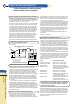
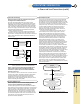
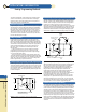
multiple power supply system. Figure 13 shows an example
of a properly connected and grounded multiple power
supply system.
Figure 13 A Properly Connected Multiple Power Supply System
Load
No. 1
Load
No. 3
Load
No. 2
C1
C2A
C
A
C2B
C3
GP
+
C
B
+
S.G.
Power Supply ”A“
+S
1
+
-S
GND
-
S.G.
Power Supply ”B“
+S
1
+
-S
GND
-
DT
DT
DT & CP
S.G = “Safety Ground” lead in power cord
GND = Power supply ground terminal
C
A
, C
B
= Power supply output capacitors removed and placed across DT’s
C1, C2, C3, = Load decoupling capacitors
1 Power supply chassis ground connection via 3rd wire
saftey ground lead and rack frame.
66 APPLICATIONS INFORMATION
ac Power and Load Connections (cont’d)
Visit our web site
http://www.agilent.com/find/power
A
B
C
D
E
F
G
H
I
K
App.
Info.