
Technical data

APPLICATIONS INFORMATION 65
ac Power and Load Connections (cont’d)
d. Multiple Loads, Two or More of Which are Individually
Grounded.
This undesirable situation must be eliminated if at all possible.
Ground loop currents circulating through the dc and load
wiring cannot be avoided so long as separate loads connected
to the same power supply or dc system have separate ground
returns as shown in Fig. 8.
One possible solution is to break the ground connection in
all of the loads and then select the dc common point using the
multiple ungrounded load alternative as in (b) above. Another
would be to break the ground connection in all but one of the
loads and select the dc common point as in alternative (c).
If there are two or more loads with ground connections that
cannot be removed and the system is susceptible to ground
loop problems, then the only satisfactory solution is to
increase the number of power supplies and to operate each
grounded load from a separate supply. Each combination of
power supply and grounded load would be treated as in
alternative (c).
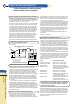
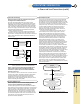
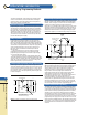
Figure 8 Improperly Connected dc Distribution System with Two
Grounded Loads forming a Ground Loop
e. Load System Floated at a dc Potential Above Ground.
It is sometimes necessary to operate the power supply output
at a fixed voltage above or below ground potential. The usual
procedure in these circumstances is to designate a dc common
point using whichever of the preceding four alternatives is
appropriate, just as though conductive grounding were to be
used. Then connect this dc common point to the dc ground
point through a 1 microfarad capacitor as shown in Figure 9.
Figure 9 Floating a Load System at a dc Potential
Above Ground
Select the dc Ground Point
STEP 6. Designate the terminal that is connected to ground
as the dc ground point.
The dc ground point can be any single terminal, existing or
added, that is conductively connected to the ground of the
building wiring system and then eventually to earth ground.
STEP 7. Connect the dc common point to the dc ground point,
making certain there is only one conductive path between
these two points.
Make this connection as shown in Figures 4, 5, 6, or 7. Make
the connection as short as possible and use a wire size such
that the total impedance from the dc common point to the dc
ground point is not large compared with the impedance from
the ground point to earth ground. Flat braided leads are some-
times used to further reduce the high frequency component of
the ground lead impedance.
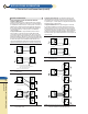
Making Remote Error Sensing Connections
Normally a power supply operating in the constant voltage
mode achieves its optimum line and load regulation, its lowest
output impedance, drift, and PARD, and its fastest transient
recovery performance at the power supply output terminals.
If the load is separated from the output terminals by any
lead length (as in Fig. 10), some of these performance
characteristics will be degraded at the load terminals-usually
by an amount proportional to the impedance of the load leads
compared with the output impedance of the power supply.
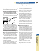
Figure 10 Load Voltage Variations Caused by Load Lead Voltage
Drops when Remote Error Sensing is not Used
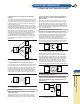
With remote error sensing, a feature included in nearly all
Agilent power supplies, it is possible to connect the input of
the voltage feedback amplifier directly to the load terminals
so that the regulator performs its function with respect to the
load terminals rather than with respect to the power supply
output terminals. Thus, the voltage at the power supply
output terminals shifts by whatever amount is necessary to
compensate for the voltage drop in the load leads, thereby
maintaining the voltage at the load terminals constant (Fig. 11).
Figure 11 Regulated Power Supply with Remote Error Sensing.
Making the Sensing Connections
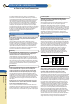
STEP 8. Remove the jumper connections between the power
supply sensing and output terminals, and connect the power
supply sensing terminals to the dc distribution terminals as
shown in Fig. 12.
Figure 12 Properly Grounded Power Supply System with
Remote Error Sensing
Power Supply
+S
Load
No 2
Load
No 1
Load
No 3
GND
S.G.
Ground
Voltage
Source
-S
+
-
Power Supply
+S
Load
GND
S.G.
CP
GP
1µf
-S
+
-
Power Supply
+S
R
L
-S
∆E
0
≠0
+
-
Power Supply
+ Sensing Lead
- Sensing Lead
+
R
L
-
∆E
0
≠0 ∆E
0
⯝0
+S
-S
Power Supply
+S
+DT
Load
No. 1
DT and CP
GP
Load
No. 2
-S
+
-
For more information in the U.S.A. call
1-800-452-4844
A
B
C
D
E
F
G
H
I
K
App.
Info.