
Technical data

Select the dc Common Point
STEP 5. Designate one of the dc distribution terminals
as the dc common point.
There should be only one dc common point in a dc system. If
the supply is to be used as a positive source, then the negative
dc distribution terminal is the dc common point. If it is to be a
negative source, then the positive dc distribution terminal is
the dc common point. Here are some additional suggestions
for selecting the best dc common point for five different
classes of loads:
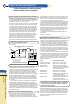
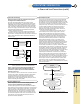
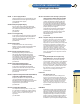
a. Single Isolated Load. A single isolated load exists when a
power supply is connected to only one load and the load
circuit has no internal connections to the chassis or ground.
If the power supply output terminals are to be used as the dc
distribution terminals, then the dc common point will be either
the positive or negative power supply output terminal (Fig. 4A).
If remote sensing is to be used and the load terminals will
serve as the distribution terminals, then either the positive or
negative load terminal will be the dc common point (Fig. 4B).
Figure 4 Preferred Ground Connections for a Single
Isolated Load
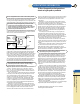
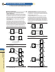
Figure 5 Preferred Ground Connections for Multiple
Ungrounded Loads
b. Multiple Ungrounded Loads. This alternative applies when
separate pairs of load leads connect two or more loads and
none of the load circuits has an internal connection to chassis
or ground (Fig. 5). Use the positive or negative dc distribution
terminal as the dc common point.
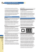
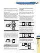
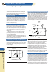
c. Single Grounded Load. When a power supply is connected
to a single load that has a necessary internal connection to
chassis or ground as in Fig. 6, or when a supply is connected
to multiple loads only one of which has a necessary internal
connection to chassis or ground as in Fig. 7, the load terminals
of the grounded load must be designated the dc distribution
terminals, and the grounded load terminal is necessarily the dc
common point.
Figure 6 Preferred Ground Connections for a Single
Grounded Load
Figure 7 Preferred Ground Connections for Multiple Loads,
Only One of Which is Grounded Internally
Power Supply
+S
Load
GND
S.G.
GP CP
A. Without Remote Sensing
S.G. = ”Safety Ground“ lead in power cord –
connected to chassis and ground terminals of
power supply, and to earth ground
GND = Power supply ground terminal
-S
+
-
Power Supply
+S
Load
GND
S.G.
GP CP
B. With Remote Sensing
-S
+
-
Without Remote Sensing
Power Supply
+S
Load
No. 1
Load
No. 2
-S
+
-
With Remote Sensing
CP
GP
S.G. GND
Power Supply
+S
Load
No. 1
Load
No. 2
-S
+
-
GP CP
S.G. GND
Power Supply
+S
Load
GND
S.G.
CP and GP
Without Remote Sensing
-S
+
-
Power Supply
+S
Load
GND
S.G.
CP and GP
With Remote Sensing
-S
+
-
With Remote Sensing
Power Supply
+S
Load
No 2
Load
No 1
Load
No 3
GND
S.G.
CP and GP
Without Remote Sensing
-S
+
-
Power Supply
+S
Load
No 2
Load
No 1
Load
No 3
GND
S.G.
CP and GP
-S
+
-
64 APPLICATIONS INFORMATION
ac Power and Load Connections (cont’d)
Visit our web site
http://www.agilent.com/find/power
A
B
C
D
E
F
G
H
I
K
App.
Info.