
Technical data

APPLICATIONS INFORMATION 63
ac Power and Load Connections (cont’d)
Connect the Load Wiring
STEP 2. Designate a single pair of terminals as the positive
and negative dc distribution terminals.
These two terminals might be the power supply output
terminals, the load terminals, or a separate pair of terminals
established expressly for distribution. If the power supply is
a short distance from the load and remote sensing will not be
used, locate the dc distribution terminals as near as possible
to the power supply output terminals. Using the power supply
output terminals themselves as the distribution terminals
results in optimum performance.
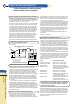
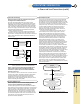
If remote sensing is to be used, locate the dc distribution
terminals as near as possible to the load terminals. Later in
the procedure, sensing leads will be connected from the power
supply sensing terminals to the dc distribution terminals as
shown in Fig. 2.
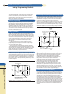
Figure 2 Location of dc Distribution Terminals with Remote
Sensing (Distribution Terminals are Shown Solid)
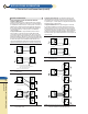
STEP 3. Connect one pair of wires directly from the power
supply output terminals to the dc distribution terminals,
and connect a separate pair of wires from the distribution
terminals to each load.
There should be no direct connection from one load to another
except by way of the dc distribution terminals. (Although for
clarity the diagrams show the load and sensing leads as
straight lines, some immunity against pick-up from stray
magnetic fields can be obtained by twisting each pair of load
leads and shielding all sensing leads.)
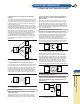
Decouple Multiple Loads
STEP 4. If required, connect a local decoupling capacitor
across each pair of distribution and load terminals.
Load decoupling capacitors are often needed when multiple
loads draw pulse currents with short rise times. To reduce high
frequency mutual coupling effects under these circumstances,
capacitors must be connected directly across the load and
distribution terminals. The capacitors used for decoupling
must be selected to have a high frequency impedance that is
lower than the impedance of the wires connected to the same
load, and their connecting leads must be kept as short as
possible to minimize impedance.
Grounding the System
Since no two ground points have exactly the same potential,
the idealized concept of a single ground potential is a snare
and a delusion. In many cases the potential difference is small,
but a difference in two ground potentials of even a fraction of a
volt could cause amperes of current to flow through a com-
plete ground loop. (Ground loop is a term used to describe any
conducting path formed by two separate connections to
ground). Ground loops can cause serious interference
problems when voltages developed by these currents are
coupled into sensitive signal circuits.
To avoid ground loop problems, there must be only one
ground return point in a power supply system. (A power
supply system includes the power supply, all of its loads,
and all other power supplies connected to the same loads).
The selection of the best ground return point depends on the
nature and complexity of the dc wiring. In large systems,
practical problems frequently tend to force compromises
with the ideal grounding concept. For example, a rack
mounted system consisting of separately mounted power
supplies and loads generally has multiple ground connections.
Each instrument usually has its own chassis tied to the third
grounding wire of its power cord, and the rack is often
connected by a separate wire to ground. With the instrument
panels fastened to the rack frame, circulating ground currents
are inevitable. However, as long as these ground currents are
confined to the ground system and do not flow through any
portion of the power supply dc distribution wiring, their effect
on system performance is usually negligible. To repeat,
separating the dc distribution circuits from any conductive
paths in common with ground currents will in general reduce
or eliminate ground loop problems. The only way to avoid
such common paths is to connect the dc distribution system to
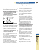
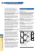
ground with only one wire. Figure 3 illustrates this concept:
dc and signal currents circulate within the dc system, while
ground loop currents circulate within the ground system.
Steps, 5, 6, and 7 make specific recommendations for avoiding
ground loop problems.
Figure 3 Isolating Ground Loop Paths from the dc system
Power Supply
+S
+DT
-DT
Load
No. 1
Keep these four load
wires as short as possible,
use large wire size
Load
No. 2
-S
+
-
Power Supply
+S
Load
-S
+
-
With One Load
With Multiple Loads
dc System
Consisting of all interconnected power supply
outputs, their dc distribution wiring and
associated load circuits.
Ground System
Consisting of all chassis for power supplies
and their load devices, their ground
terminals, safety ground,
ac ground wiring, rack frames, etc.
dc Common Point (CP)
dc ground
connection
dc Ground Point (CP)
All eventually lead
to earth ground
Only one wire or connection
is permitted if ground loop currents
are to be kept out of dc system
For more information in the U.S.A. call
1-800-452-4844
A
B
C
D
E
F
G
H
I
K
App.
Info.