
Technical data

A modern stabilized dc power supply is a versatile high
performance instrument capable of delivering a constant or
controlled output reliably and with little attention. But to take
full advantage of the performance characteristics designed
into a supply, certain basic precautions must be observed
when connecting it for use on the lab bench or installing it in
a system. Factors such as wire ratings, system grounding
techniques, and the particular way that ac input, dc output,
and remote error sensing connections are made can contribute
materially to obtaining the stable, low noise output expected
by the user. Careful attention to the following guidelines
can help to ensure the trouble free operation of your
Agilent power supply.
ac Power Input Connections
Wire Rating
RULE 1. When connecting ac power to a power supply, always
use a wire size rated to carry at least the maximum power
supply input current.
If a long cable is involved, make an additional check to
determine whether a still larger wire size might be required
to retain a sufficiently low impedance from the service outlet
to the power supply input terminals. As a general guideline,
input cables should be of sufficient size to ensure that the
voltage drop at maximum rated power supply input current
will not exceed 1% of the nominal line voltage.
Continuity
RULE 2. Maintain the continuity of the ac, acc, and grounding
wires from the ac power outlet to the power supply input
terminals without an accidental interchange.
Interchanging the ac and grounding wires may result in the
power supply chassis being elevated to an ac potential equal
to the input line voltage. If the chassis is grounded elsewhere,
the result may be no worse than some blown fuses. But if the
chassis is not grounded, the result could be a potentially lethal
shock hazard. Confirm that the chassis is grounded by the
grounding wire.
Transformers
RULE 3. If an autotransformer or an isolation transformer is
connected between the ac power source and the power
supply input terminals, it should be rated for at least 200%
of the maximum rms current required by the power supply.
The transformer must have a higher rating than would be
suggested by the supply’s rms input current because a power
supply input circuit does not draw current continuously. Input
current peaks can cause a smaller transformer to saturate,
resulting in failure of the supply to meet its specifications at
full output.
RULE 4. Be sure to connect the common terminal of an auto-
transformer to the acc (and not the ac) terminals of both the
power supply and the input power line.
If acc is not connected to the common terminal of the auto-
transformer, the power supply’s input acc terminal will have a
higher than normal ac voltage connected to it, contributing to
a shock hazard and, in some instances, a greater output ripple.
ac Line Regulator
RULE 5. Do not use an ac line regulator at the input to a
regulated power supply without first checking with the
power supply manufacturer.
Some regulators tend to increase the impedance of the line
in a resonant fashion and can cause power supplies to
malfunction, particularly if they use SCR or switching
regulators or preregulators. Moreover, since the control action
of many line voltage regulators is accompanied by a change in
the output waveshape, their advantage in providing a constant
rms input to a power supply is small. In fact these changes in
waveshape are often just as disruptive in causing power
supply output changes as the original line voltage amplitude
changes would have been.
Load and Remote Error Sensing Connections
Making Load Connections to One Power Supply
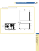
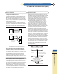
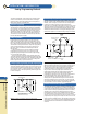
The simplest and most common example of improper load
wiring is shown in Figure 1. The voltage at each load depends
on the current drawn by the other loads and the voltage drops
they cause in some portion of the load leads. Since most load
currents vary with time, an interaction among the loads
results. This interaction can sometimes be ignored, but in
most applications the resulting noise, pulse coupling, or
tendency toward inter-load oscillation is unacceptable.
The following thirteen steps describe a recommended
procedure for connecting the load wiring, grounding the
system in a manner that avoids troublesome ground loops,
and making connections for remote error sensing.
Figure 1 Improper load connections
STEP 1. Select a load wire size that, as an absolute minimum,
is heavy enough to carry the power supply output current that
would flow if the load terminals were short-circuited.
This is the minimum, however. Impedance and coupling
considerations usually dictate the use of load wires larger than
would be required just to satisfy current rating requirements.
In general, the power supply performance degradation seen at
the load terminals becomes significant when the wire size and
length result in a load wire impedance comparable to or greater
than the effective output impedance of the power supply. Refer
to a copper wire resistance table to see if a larger wire size
might have to be used to attain an impedance comparable to
or smaller than the output impedance of the power supply.
If multiple loads are supplied from a pair of dc distribution
terminals not located at the power supply terminals, it is
necessary to consider separately the mutual impedance of
the wires connecting the power supply to the distribution
terminals and the additional impedance of the wires to each
individual load. The mutual impedance presents an opportunity
for a variation of one load current to cause a dc voltage
variation at another load. Fortunately this mutual impedance
can be effectively reduced at dc and at low frequencies by
using remote error sensing, as will be described later.
Load
No1
Power Supply
+
-
Load
No2
Load
No3
62 APPLICATIONS INFORMATION
ac Power and Load Connections
Visit our web site
http://www.agilent.com/find/power
A
B
C
D
E
F
G
H
I
K
App.
Info.