
Technical data

APPLICATIONS INFORMATION 61
10 Most frequently asked questions
about using dc power products
For more information in the U.S.A. call
1-800-452-4844
7) Can I use Agilent Electronic Loads in series and in parallel?
Agilent electronic loads are designed to be operated in parallel
for more current, but NOT in series for more voltage. Loads
are fully protected against damage from current overloads, but
will be damaged by voltage above the maximum voltage rating.
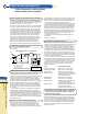
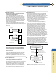
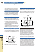
8) I must test a 1 volt power supply using a constant current
load and I want to use Agilent Electronic Loads. But the
Agilent load meets all of its dynamic specs with no derating
on down to 3 volts. Below 2 volts, the Agilent load current
must be linearly derated. What can I do?
Use a boost supply in series with the UUT. The load will now
meet all its specs with no derating, because it always operates
above 3 volts. (see the illustration below)
The boost supply can be a low-cost fixed output 3 V or 5 V
supply with a current rating at least as high as the maximum
peak load current needed. The 6641A (8 V, 20 A), 6651A (8 V,
50 A), 6671A (8 V, 220 A), or 6681A (8 V, 580 A) are all excellent
choices. The voltage setting of a programmable boost supply
should be set to 3 volts, and the current limit set to full scale.
Select a boost power supply with low p-p ripple and noise.
The constant current load will compensate for low-frequency
p-p ripple and noise below a few kHz, but high frequency
ripple and noise from the boost will appear across the UUT.
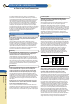
9) Why are Agilent’s Electronic Loads constant resistance
resolution speced in ohms on the low resistance range,
but in mSiemens on the two higher ranges?
In general, Agilent’s Electronic Loads are not a conventional
“resistor”. The loads consist of IC’s, capacitors, resistors,
FETs, etc. They were designed with two major circuits, a cv
and cc circuit. These circuits are used to simulate resistance
on the two upper ranges.
First, it is necessary to understand why there is a difference
in the way in which the ranges are specified (mohms or mS).
The constant resistance (CR) mode in the load actually
operates using either the constant current (CC) or constant
voltage (CV) circuits inside the load. The lowest CR range
uses the CV regulating circuits, while the two higher ranges
use the CC regulating circuits. It is because of these differ-
ences in the circuits used to regulate the load input that the
specifications need to be different.
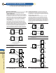
When the CV circuits are used, the load can be viewed as
many resistors, all the same value (the resolution), in series to
produce the desired resistance. Then, changing the resistance
is like changing the number of discrete resistors in series.
Therefore, the resolution is the value of one of these series
resistors, and putting resistors in series changes the resistance
measured in ohms. For the 60501B, the “discrete resistor” or
resolution that can be programmed is 0.54 mohms in the
2 ohm range.
When the CC circuits are used, the load can be viewed as
many resistors, all the same value (the resolution), in parallel
to produce the desired resistance. Then, changing the
resistance is like changing the number of discrete resistors in
parallel. Therefore, the resolution is the value of one of these
parallel resistors, and putting resistors in parallel changes
the conductance measured in siemens. For the 60501B, the
“discrete resistor” or resolution that can be programmed is
0.14 mS (=7.14 kohms).
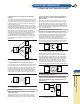
For example, in the 2 kohm range, you can program the
load input from 2 ohms to 2 kohms (0.5 S to 0.5 mS) with a
resolution of 0.14 mS. This would be the equivalent of starting
with about 3568 7.143 kohm resistors in parallel with each
other, and in parallel with a 2 kohm resistor, and removing one
at a time until you had only the 2 kohm resistor left.
Note that the resolution of the conductance is constant at
0.14 mS, however, the resolution of the total parallel resistance
is not constant. It depends on how many resistors you have in
parallel.
If you have two 7.143 kohm resistors in parallel and remove
one, the resolution looks like 3571.5 ohms. If you have
3568 7.143 kohm resistors in parallel and remove one, the
resolution looks like (7143/3567) - (7143/3568) = 0.561 mohms.
But the conductance resolution is constant at 0.14 mS.
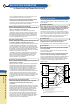
10) Can Agilent power supplies be programmed from 0 to full
output voltage using a 0 to 10 V signal source?
Yes, many Agilent power supplies feature remote voltage
programming or analog programming capability. However,
there is a potential danger in analog programming any power
supply, especially a high voltage supply. If the 0 to 10 V pro-
gramming source is a typical, non-isolated, low-cost, digital-to-
analog converter (DAC), it is probably grounded through its
digital inputs and/or through the computer’s internal power
supplies, which are grounded through the computer’s power
cord. It’s easy to overlook this, and the mistake can be very
expensive.
If the DAC is non-isolated (or isolated only up to 42 V above
ground) and one of the output terminals of the power supply is
grounded, either directly or through the UUT, the output
capacitor of the power supply can discharge through the com-
puter backplane, motherboard, and the I/O common through
the computer power cord ground. The resulting high current
may even last long enough to vaporize the thin ground tracks
on some or all of the printed circuit boards in the PC.
Be sure the programming source is electrically isolated, is
operated from isolated power supplies, and is rated for float-
ing voltages up to the full output voltage of the programmed
supply. This is necessary so no one is hurt, and no equipment
is damaged, no matter which output terminal of the power
supply or UUT is grounded.
For more information, refer to the topic on Constant Voltage
Programming with Variable Voltage Gain on page 64.
For additional questions and answers visit our web site
at www.agilent.com/find/answers
UUT
Boost
Supply
-
Out
- Sense
+ Sense
+ Out
+ Out
+ Sense
I
Load
Agilent
Load
+
Out
+ Sense
- Sense
- Out
- Sense
- Out
A
B
C
D
E
F
G
H
I
K
App.
Info.