Power Products Catalog 2001Application Information and Technical Data for: • Mobile Communications dc Sources • dc Power Supplies • dc Electronic Loads • ac Power Solutions • Solar Array Simulators Need Help with Power Products? In the US only call: 1 800 452-4844 www.agilent.
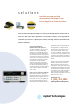
solutions to match your new test and measurement challenges. From Power Supplies to Power Solutions One quick browse through this catalog will convince you that Agilent power products offer so much more than simple power generation. In each product category, we’ve integrated the capabilities you need for a complete power solution, including extensive measurement and analysis capabilities.
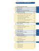
TA B L E O F C O N T E N T S Selecting a System Power Supply 2 A Application Index 3 B Selection Index 4 C Feature Descriptions and Selection Index 6 D 8-26 E System dc Power Supplies Single-Output: 30 W to 5,000 W 8-19 Precision Measurement, Single & Dual-Output:40 W to 100 W 9-12 Mobile Communication dc Sources: 40 W to 100 W 10-11 Telecommunications dc Source: 2,000 W 17 Single-Output, Autoranging: 200 W to 1,000 W 19 Multiple-Output: 25 W to 100 W Precision Measurement, Multiple
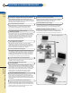
2 SELECTING A SYSTEM POWER SUPPLY A Selecting a System 12 Factors to Consider when Selecting a System Power Supply 1) Does the power supply performance meet your requirements? 10) How easy is it to verify proper operation? Agilent 6600, 6800, and 66000 Series offer low output noise among the best in their power ranges - allowing you to make even the most critical measurements. Active circuits ensure fast up and down programming, regardless of the load.
APPLICATION INDEX 3 A • • • Wir Index Page No. 6611C-6614C 9 66309B/D, 66311B/D 66332A 10 • 6631B-6634B 12 • • E3632A-E3634A 13 • • • Application Agilent Model No. • • eless testing communicati ons UPS Te sting Simula te of sola elec. chara r array ct.
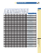
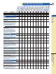
SELECTION INDEX 4 Available on Special Order A B C Selection http://www.agilent.com/find/power Visit our web site Index SINGLE OUTPUT S I N G L E O U T P U T GPIB System Power Supplies Max volts (dc) Max amps (dc) 5 6.7 7 8 8 8 8 8 8 8/20 8/20 8/20 8/20 15 15/12 15/12 15 15/30 20 20 20 20 20 20 20 20 20 20 21 25/30 32 35 35 35 35/60 35/60 35/60 40 50 50 50/25 60 60 60 60 60 60 65 100 100 120 120 120 130 200 200 500 875 30 120 5 10 20 50 220 580 3/1.5 5/2.5 8/4 20/10 3 3/1.5 3/1.
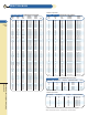
SELECTION INDEX M U LT I P L E O U T P U T 5 GPIB System Power Supplies (with a Rectangular Output Operating Boundary) Range 1 Range 2 Max. Max. Max. Max. Max. watts volts amps volts amps per (dc) (dc) (dc) (dc) output A Outputs for each Agilent model number 6621A 6622A 6623A 6624A 6625A 6626A 6627A 6628A 6629A E3631A E3646A E3647A E3648A E3649A page 22 page 22 page 22 page 22 page 21 page 21 page 22 page 21 page 21 page 20 page 23 page 23 page 23 page 23 6 7 5 0.015 50 0.
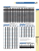
Max Power Max Voltage Max Current Page 100 V 10 A 12 200 W 120 V 20 A 14 500 W 120 V 50 A 15 2000 W 120 V 220 A 16 5000 W 40 V 875 A 18 1200 W 40 - 100 W 200 V 20V 16 A 5A 24 10 • • • • • • • • • 6620 S eries Precis io Multip n le Outp 6670 S eries Single Outpu t 50 V 2A 22 6650 S eries Single Outpu t 50 V 10 A 21 200 - 1000 W 40 & 50 W 40 & 80 W 25 & 50 W 80 & 100 W 6640 S eries Single Outpu t 100 V 5A 9 ut 6630 S eries Single Outpu t 66000 Modula r Power System C D 6680 S eries
500 V 120 A 19 100 V 5A 9 50 V 10 A 21 50 V 2A 22 100 V 10 A 12 2000 W 120 V 220 A 16 5000 W 40 V 875 A 18 1200 W 200 V 16 A 24 7 66300 Series Mobil Comm e unicati ons E3640A Series Single & Dual Output 500 W 120 V 50 A 15 66000 Modula r Power System 200 W 120 V 20 A 14 6680 S eries Single Outpu t 6670 S eries Single Outpu t ut 6630 S eries Single Outpu t 6620 S eries Precis Multip ion le Outp 200 - 1000 W 40 & 50 W 40 & 80 W 25 & 50 W 80 & 100 W 6650 S eries Single Outpu t Max Power Max V
8 AGILENT SYSTEM dc POWER SUPPLIES Single-Output: 30 W to 80 W A B C D Single-Output, Dual-Range Low noise/excellent line and load regulation GPIB/RS-232 standard SCPI (Standard Commands for Programmable Instrument) compatible Front and rear output terminals Overvoltage protection Remote sense at rear output E3640A, E3641A, E3642A, E3643A, E3644A, E3645A E System dc Power Supplies Agilent E3640A – 45A Single Output Standard remote interface The new E3640A-series programmable dc power supplies are 30
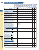
AGILENT SYSTEM dc POWER SUPPLIES 9 Precision Measurement, Single-Output: 40 W and 50 W Precision low current measurement A Low output noise B High speed programming C GPIB and RS-232 interface 6611C - 6614C SCPI (Standard Commands for programmable instruments) VXIplug&play drivers D E S P E C I F I C AT I O N S (at 0˚ to 55˚ C unless otherwise specified) System dc Power Single Output System 6611C 6612C 6613C 6614C 0 to 8 V/0 to 5 A 0 to 20 V/0 to 2 A 0 to 50 V, 0 to 1 A 0 to 100 V/0 to
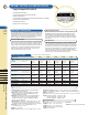
AGILENT SYSTEM dc POWER SUPPLIES 10 Mobile Communications dc sources-40 W to 100 W Ideal for wireless/portable product test A Programmable output reisistance (66319B/D and 66321B/D only) B Dynamic pulse measurement High-speed programming C SCPI (Standard Commands for Programmable Instruments) D GPIB interface1, VXIplug&play drivers 66309B/D, 66311B/D E System S P E C I F I C AT I O N S dc Power (at 0˚ to 55˚ C unless otherwise specified) 3 Agilent Mobile Communications dc Sources Supplies
AGILENT SYSTEM dc POWER SUPPLIES 11 Mobile Communications dc sources-40 W to 100 W A B 3 C 66321B/D, 66319B/D D E 3 dc Floating Voltage: Output terminals can be floated up to ±50 Vdc Standard: 104 to 127 Vac 47 to 63 Hz Opt 100 87 to 106 Vac, 47 to 63 Hz Opt 220 191 to 233 Vac, 47 to 63 Hz Opt 230 207 to 253 Vac, 47 to 63 Hz Opt 020 Front-panel Binding Posts (66332A only) Opt 521 Solid State Relays (66309B/D, 66319B/D) Opt 760 Isolation and Reversal Relays (66332A only) *Opt 1CM Rack-mount Kit 66309
12 AGILENT SYSTEM dc POWER SUPPLIES Precision Measurement Single-Output: 80 W and 100 W A B Precision low current measurement Low-output noise High-speed programming C GPIB and RS-232 interface D SCPI (Standard Commands for Programmable Instruments) 6631B - 6634B VXIplug&play drivers E System S P E C I F I C AT I O N S (at 0˚ to 55˚ C unless otherwise specified) dc Power Supplies Output ratings Voltage/Current Programming accuracy at 25˚C ±5˚C Voltage/+ Current Ripple and noise (20 Hz to 2
AGILENT SYSTEM dc POWER SUPPLIES 13 Single-Output: 120 W to 200 W E3632A Features: E3633A and E3634A Features: 105/120 watts of power 160/200 watts of power 15 V, 7 A/30 V, 4 A single output dual range Single-output, dual range E3632A, E3633A, E3634A A B Low noise/excellent regulation Front and rear output terminals Two digital meters Low noise/excellent regulation C Remote sense, OVP & OCP capability Remote sense, OVP & OCP capability D 16-bit programming resolution 16-bit programming res
14 AGILENT SYSTEM dc POWER SUPPLIES Single-Output: 200 W Linear output regulation A Fast up- and down-programming B Complete front-panel control calibration and display C Remote programming and sensing SCPI (Standard Commands for Programmable Instruments) 6641A - 6645A Fan-speed control to minimize acoustic noise D Low ripple and noise E Over-voltage and over-current protection Serial link connects up to 16 units to one HP-IB address System VXIplug&play drivers dc Power Supplies S P E C I
AGILENT SYSTEM dc POWER SUPPLIES 15 Single-Output: 500 W Complete front-panel control, calibration and display Remote programming and sensing A Fan-speed control to minimize acoustic noise B Low ripple and noise Over-voltage and over-current protection C Linear output regulation 6651A - 6655A Fast up-and down-programming D SCPI (Standard Commands for Programmable Instruments) E Serial link connects up to 16 units to one HP-IB address System VXIplug&play drivers dc Power Supplies (at 0˚ to 5
16 AGILENT SYSTEM dc POWER SUPPLIES Single-Output: 2,000 W Low ripple and noise A B Fast up- and down-programming SCPI (Standard Commands for Programmable Instruments) Complete front-panel control, calibration and display C Remote programming and sensing D Fan-speed control to minimize acoustic noise 6671A - 6675A Low Ripple and Noise E Over-voltage and over-current protection Serial link connects up to 16 units to one HP-IB address System dc Power Supplies VXIplug&play drivers S P E C I F I C
AGILENT SYSTEM dc POWER SUPPLIES 17 Telecommunications dc source-2,000 W Low ripple and noise A Fast up-and down-programming SCPI (Standard Commands for Programmable Instruments) Complete front-panel control, calibration and display E4356A B Remote programming and sensing C Fan-speed control to minimize acoustic noise D Over-voltage and over-current protection Serial link connects up to 16 units to one HP-IB address E VXI plug&play drivers System Also suitable for non-telecom applications dc P
18 AGILENT SYSTEM dc POWER SUPPLIES Single-Output: 5,000 W A “One Box” solution: includes V and I read-back B Fast up-and down-programming C High-accuracy current programming and read back D E Low ripple and noise Standard Commands for Programmable Instruments (SCPI) 6680A - 6684A Selectable compensation for inductive loads Serial link connects up to 16 units to one HP-IB address VXIplug&play drivers System dc Power S P E C I F I C AT I O N S (at 0˚ to 55˚ C unless otherwise specified) Suppli
AGILENT SYSTEM dc POWER SUPPLIES 19 6033A, 6038A Single-Output, Autoranging: 200 W to 1,000 W Features: A Autoranging Output: Standard Commands for Programmable Instruments VXIplug&play drivers Volts 6030A, 6031A, 6032A, 6035A B P1 V1 C P2 V2 V3 P3 D I1 I2 I3 Amps E System S P E C I F I C AT I O N S (at 0˚ to 55˚ C unless otherwise noted) dc Power Supplies System Autorangers 6030A 6031A 6032A 6033A 6035A 6038A Output ratings Voltage Current 0 to 200 V 0 to 17 A 0 to 20 V 0
20 AGILENT SYSTEM dc POWER SUPPLIES Multiple-Output: 25 W and 30 W A E3631A Features: B Triple outputs C Dual voltage and current meters Total 80 watts of power E3631A SCPI (Standard Commands for Programmable D Instruments) compatible E GPIB/RS-232 standard System dc Power Supplies E3631A Triple-Output Front Panel Operation The E3631A is a triple-output programmable dc power supply designed to meet the most exacting engineering requirements with traditional Agilent quality and reliability
AGILENT SYSTEM dc POWER SUPPLIES 21 Precision Measurement Multiple-Output: 25 W and 50 W 2 or 4 independent isolated outputs A Dual-range linear outputs 6625A, 6626A, 6628A, 6629A Low ripple and noise B Fast up- and down-programming C 14-bit programming and readback of voltage and current D Current sourcing and sinking E S P E C I F I C AT I O N S (at 0˚ to 55˚ C unless otherwise specified) System dc Power Output Power Output combinations for each model (total number of outputs) Programmi
22 AGILENT SYSTEM dc POWER SUPPLIES Multiple-Output: 40 W and 80 W 2, 3, or 4 independent isolated outputs A Dual-range linear outputs B Low ripple and noise C Readback of output voltage and current D Current sourcing and sinking Fast up- and down-programming 6621A-6624A, 6627A E System dc Power S P E C I F I C AT I O N S (at 0˚ C to 55˚ C unless otherwise specified) Supplies 80-watt output 80-watt output 0 to 7 V, 0 to 5 A 0 to 20 V, 0 to 2 A 0 to 20 V, 0 to 2 A 0 to 50 V, 0 to 0.
AGILENT SYSTEM dc POWER SUPPLIES 23 Multiple-Output: 60 W to 100 W Dual-Output, Dual-Range Low noise/excellent line and load regulation GPIB/RS-232 standard SCPI (Standard Commands for Programmable Instrument) compatible Front and rear output terminals Overvoltage protection Remote sense at rear output E3646A, E3647A, E3648A, E3649A A B C D E System dc Power Agilent E3646A – 49A Dual Output Standard remote interface The new E3640A-series programmable dc power supplies are 60W/100W dual output dc powe
24 AGILENT SYSTEM dc POWER SUPPLIES Modular Power System: 1,200 W per mainframe High density: eight slots in 7 inches of rack space A Output sequencing B Low ripple and noise High-accuracy read-back of voltage and current over GPIB C Standard Commands for Programmable Instruments (SCPI) D Optional keyboard and display unit E System dc Power Serial link to connect two mainframes at one GPIB address Optional isolation and polarity-reversal relays 66000A (mainframe) 66001A (keyboard) Built-in self
25 A B C D E dc Floating Voltage: Output terminals can be floated up to ±240 Vdc from chassis ground Remote Sensing: Up to half the rated output voltage can be dropped across each load lead. Add 2 mV to the voltage load regulation specification for each 1–V change in the negative output lead caused by a load current change.
26 AGILENT SOLAR ARRAY SIMULATOR: 480 W The E4350B/E4351B simulates the output characteristics of a A satellite’s solar panels as it moves from darkness to light. B C E4350B, E4351B D E System dc Power Supplies Agilent Solar Array Simulator The Agilent one-box Solar Array Simulator (SAS) is a dc power source that simulates the output characteristics of a solar array.
AGILENT dc POWER SUPPLIES 27 Single Output - 24 W to 60 W E3610A, E3611A, E3614A, E3615A, E3616A and E3612A features: and E3617A features: Dual ranges Digital voltage and Digital voltage and current meters current meters E3610A-E3612A, E3614A-E3617A Overvoltage protection 10-turn potentiometer Remote sensing Linear power supply Remote analog programming Linear power supply E3610A, E3611A, E3612A E3614A, E3615A, E3616A, E3617A These popular low-cost CV/CC bench supplies are designed for gen
28 AGILENT dc POWER SUPPLIES Single-Output Manually Controlled: 200 W A Constant-voltage, constant-current operation Complete front-panel control calibration and display B Remote programming and sensing C Fan-speed control to minimize acoustic noise Low ripple and noise D 6541A-6545A Over-voltage and over-current protection E S P E C I F I C AT I O N S F Manually 6541A 6542A 6543A 6544A 6545A Output ratings Output voltage Output current (40˚ C) Maximum current (50˚ C/55˚ C) 0 to 8 V 0
AGILENT dc POWER SUPPLIES 29 Single-Output Manually Controlled: 500 W Constant-voltage, constant-current operation Complete front-panel control calibration and display A Remote programming and sensing B Fan-speed control to minimize acoustic noise C Low ripple and noise 6551A-6555A D Over-voltage and over-current protection E (at 0˚ to 55˚ C unless otherwise specified) S P E C I F I C AT I O N S 6551A 6552A 6553A 6554A 6555A Output ratings Output voltage Output current (40˚ C) Maximum cu
30 AGILENT dc POWER SUPPLIES Single-Output Manually Controlled: 2000 W A Constant-voltage, constant-current operation Complete front-panel control calibration and display B Remote programming and sensing C Fan-speed control to minimize acoustic noise D 6571A-6575A Low ripple and noise Over-voltage and over-current protection E S P E C I F I C AT I O N S F 6571A 6572A 6573A 6574A 6575A 0 to 8 V 0 to 220 A 0 to 20 V 0 to 100 A 0 to 35 V 0 to 60 A 0 to 60 V 0 to 35 A 0 to 120 V 0 to 18 A
AGILENT dc POWER SUPPLIES 31 Single-Output, Autoranging: 200 W to 1,000 W Auto-series, auto-parallel operation Autoranging Output: A Complete front panel control/display V1 Constant-voltage, constant-current 6023A, 6028A Volts operation Remote programming and sensing P1 P2 V2 V3 I1 Ten-turn voltage and current controls I2 P3 C I3 D Amps E 6010A, 6011A, 6012B, 6015A S P E C I F I C AT I O N S (at 0˚ to 55˚ C unless otherwise noted) 6010A 6011A 6012B 6023A 6015A 6028A Output rating
32 AGILENT dc POWER SUPPLIES Multiple-Output: 35 W and 50 W A B C D E3620A Features: Low noise, excellent regulation Two isolated power supplies Two digital meters Linear power supply 10-turn potentiometer E3630A Features: Low noise, excellent regulation Auto-tracking Two digital meters Linear power supplies Triple Outputs E3620A, E3630A E F Manually E3620A, E3630A E3630A These multiple output power supplies have 0.
AGILENT POWER SUPPLY RELAYS 33 Relay Devices Relay accessories to isolate load from dc output A Switch and sequence power and sense leads dc output polarity reversal (59511A) B C D 59510A, 59511A E Agilent Technologies 59510A and 59511A are relay devices designed for control from 66xxA and 603xA power supplies.
34 AGILENT dc ELECTRONIC LOADS Features for Increased Test Throughput: Program load input values more than 10 times faster. Load commands can be stored in the instrument, so they can be executed at maximum rate during runtime. Triggers can be used to begin preloaded test routines without any computer interaction. N3300A Multiple load modules can be simultaneously triggered to assume individual preprogrammed levels. Measurement data can be buffered in the load, and read back to the computer in one array.
AGILENT dc ELECTRONIC LOADS Optimizing System Throughput 35 Constant Current The N3300A Series electronic loads are Agilent Technologies’ fastest electronic loads. In addition, there are many new features that will allow the system designer to further increase throughput. Power Supply Load Regulation Testing Battery Capacity Testing Capacitor Discharging V Sequences of input settings can be downloaded to the load during system set-up. Then they can be repetitively accessed during runtime.
36 AGILENT dc ELECTRONIC LOADS S P E C I F I C AT I O N S (at 0˚ to 55˚ C unless otherwise specified) N3302A N3303A N3304A N3305A N3306A Amperes 0 to 30 A 0 to 10 A 0 to 60 A 0 to 60 A 0 to 120 A Volts 3 to 60 V 3 to 240 V 3 to 60 V 3 to 150 V 3 to 60 V (at 40˚C) 150 W 250 W 300 W 500 W 600 W 3 A / 30 A 1 A / 10 A 6 A / 60 A 6 A / 60 A 12 A / 120 A Regulation 10mA 8mA 10mA 10mA 10mA Low Range Accuracy 0.1% + 5 mA 0.1% + 4 mA 0.1% + 7.5 mA 0.1% + 7.5 mA 0.
AGILENT dc ELECTRONIC LOADS 37 S UPPLEMENTAL C HARACTERISTICS Programming Resolution Readback Resolution Programmable Slew Rate N3302A N3303A N3304A N3305A N3306A Constant Current Mode 0.05mA/0.5mA 0.02mA/0.2mA 0.1 mA/1 mA 0.1mA /1 mA 0.2 mA/2 mA Constant Voltage Mode 0.1 mV/1 mV 0.4 mV/4 mV 0.1 mV/1 mV 0.25 mV/2.5 mV 0.1 mV/1 mV Constant Resistance Mode 0.07/0.7/7/70 m Ω 0.82/8.2/82 m Ω 0.035/0.35/3.5/35 m Ω 0.085/0.85/8.5/85 m Ω 0.0175/0.175/1.75/17.5 m Ω Current 0.05 mA/0.
38 AGILENT dc ELECTRONIC LOADS GPIB control of current, voltage, and resistance GPIB readback of current, voltage, and power Built-in pulse waveform generation with programmable amplitude, frequency, duty cycle, and slew rate Continuous and pulse modes Full protection from overcurrent, overvoltage, overpower, 6060B and 6063B overtemperature, and reverse polarity Electronic calibration Trigger for external synchronization Analog voltage control in constant current mode Parallel units in constant current
AGILENT dc ELECTRONIC LOADS System or Manual Applications 39 Constant Current Agilent dc electronic loads are equally suitable for manual use on the bench. The front-panel LCD meters indicate voltage, current, and power readings. The full-function front-panel keypad allows easy, repeatable, and reliable control of the load when it is used manually. Six volatile user-definable states allow you to easily save settings for later recall.
40 AGILENT dc ELECTRONIC LOADS S P E C I F I C AT I O N S Amperes Volts Maximum power (at 40˚ C) Constant current mode Ranges Accuracy Regulation Constant voltage mode Accuracy Regulation (w/remote sense) Constant resistance mode Ranges Accuracy 6060B, 60502B 6063B, 60503B 60501B 60504B 60507B 0 to 60 A 3 to 60 V 300 W 0 to 10 A 3 to 240 V 250 W 0 to 30 A 3 to 60 V 150 W 0 to 120 A 3 to 60 V 600 W 0 to 60 A 3 to 150 V 500 W 0 to 6 A, 0 to 60 A 0.1% ±75 mA 10 mA 0 to 1 A, 0 to 10 A 0.
AGILENT dc ELECTRONIC LOADS 41 Supplemental Characteristics (cont’d) 6060B, 60502B 6063B, 60503B 60501B 60504B 60507B 10 kHz (–3 dB frequency) 10 kHz (–3 dB frequency) 10 kHz (–3 dB frequency) 10 kHz (–3 dB frequency) 10 kHz (–3 dB frequency) 4.5% ±75 mA 4.5% ±250 mA 100 ppm/˚C ±6 mA/˚C 0.8% ±200 mV 100 ppm/˚C ±1 mV/˚C 0 to 10 V 3% ±8 mA 3% ±20 mA 150 ppm/˚C ±1 mA/˚C 0.5% ±150 mV 120 ppm/˚C ±10 mV/˚C 0 to 10 V 4.5% ±40 mA 4.5% ±130 mA 100 ppm/˚C ±3 mA/˚C 0.
42 AGILENT ac POWER SOLUTIONS 375 VA - 4800 VA Ready to use “one-box” ac power source/analyzer ac mains design verification system for sourcing and measuring Capable of compliance-grade regulatory tests High peak current capability Programmable output impedence* Graphical user interface software Three year warranty Built-in GPIB and RS232 interfaces (SCPI programming) VXI plug&play drivers, HP VEE, NI LabView (Top) 6811B, 6812B, 6813B (Bottom) 6814B, 6834B Built-in harmonic analysis capability 400 Hz pow
AGILENT ac POWER SOLUTIONS 43 ac Power Solutions (cont’d) A Key Features Easy ATE integration Sine, square, and up to 12 user-defined waveforms Programmable voltage, current limit, frequency, phase, and distortion (clipped sinewave) Programmable dc output (6811B, 6812B, 6813B) Programmable output impedance (6811B, 6812B, 6813B) Voltage and frequency slew control Power line disturbance simulation (sag, surge, dropout, clipping, and event programming) Independent phase control (6834B only) Measurement of
44 AGILENT ac POWER SOLUTIONS ac Power Solutions (cont’d) A (per phase for a sine wave with a resistive load at 0º to 40º C, within an output frequency range of 45 Hz to 1000Hz, and in ac coupled mode after a 30 minute warm-up unless otherwise noted. Note: For 6814B and 6834B output voltage must be at least 50% of range.
AGILENT ac POWER SOLUTIONS 45 ac Power Solutions (cont’d) S P E C I F I C AT I O N S (CONTINUED) (per phase for a sine wave with a resistive load at 0º to 40º C, within an output frequency range of 45 Hz to 1000Hz, and in ac coupled mode after a 30 minute warm-up unless otherwise noted. Note: For 6814B and 6834B output voltage must be at least 50% of range.)1 A B 6811B 6812B 6813B 6814B 6834B 0.03% + 100 mV3 0.05% + 150 mV 3 0.03% + 100 mV3 0.05% + 150 mV3 0.03% + 100 mV3 0.05% + 150 mV3 0.
46 AGILENT ac POWER SOLUTIONS ac Power Solutions (cont’d) A SUPPLEMENTAL CHARACTERISTICS (non-warranted characteristics determined by design that are useful in applying the product) B 6811B 6812B 6813B 6814B 6834B Average programming accuracy (% of output + offset) rms current 1.2% + 50 mA 1.2% + 50 mA 1.2% + 50 mA 0.2% + 80 mA 0.2% + 80 mA (1⌽) 0.
ac POWER SOLUTIONS 47 screen shots A B C D E Inrush Current Measurement Ringer Voltage (dc + ac) Generation F H ac Power Quasi-Stationary Harmonics Summary Harmonic Measurement Result Solutions For more information in the U.S.A.
48 ac LINE VOLTAGE & CORD OPTIONS Choosing ac Line Voltage and Cord Options for your Agilent Power Products A B C D E 7 EASY STEPS FOR CHOOSING LINE CORD OPTIONS Determine the voltage option STEP 1 STEP 2 Go to table 1a. If the standard Find the line voltage is model number not correct, of the product use table 1b to you are order- determine ing. Note the which of the standard line available voltage. If it is options best correct you do matches the not need to available line specify a line voltage.
ac LINE VOLTAGE & CORD OPTIONS 49 Choosing ac Line Voltage and Cord Options for your Agilent Power Products A TABLE 1 B - L INE V OLTAGE C OVERAGE OF V ARIOUS S INGLE P HASE O PTIONS Note: Consult specific product listing above for options availability.
50 ac LINE VOLTAGE & CORD OPTIONS Choosing ac Line Voltage and Cord Options for your Agilent Power Products A B C D E High Power Products There are several factors which limit the amount of power which can be readily drawn from a normal branch circuit. For example, in the U.S., the typical 115/120 Vac branch circuit has a circuit breaker rated for 15 A. For industrial applications, 20 A service is commonly available.
ac LINE VOLTAGE & CORD OPTIONS 51 Choosing ac Line Voltage and Cord Options for your Agilent Power Products A T A B L E 3C - T E R M I N AT E D L I N E C O R D S Option 841 Option 842 Option 844 B (line cords with plugs) C Option 845 1.5-mm2 wire size; harmonized cordage with IEC 309, 16-A, 220-V plug. Suggested for use in Denmark, Switzerland, Austria, China and other countries not listed. 12 AWG; UL-listed, CSAcertified; with NEMA 6-20P, 20-A, 250-V plug.
52 DIMENSION DRAWINGS A Agilent Models: 6010A, 6011A, 6012B, 6015A, 6030A, 6031A, 6032A, 6035A B Top Terminal Strip Detail C VM Screw Size M3.5 x 0.6 IM D E M VP 425mm 16.75" IP P B6 B1 +S Does not apply to models 6010A, 6011A, & 6021B 2.5mm 0.1" 421.6mm 16.6" -S 12.7mm 0.5" 128mm 5.04" 132.6mm 5.2" F 77mm 3.03" Side Rear 12.7mm 0.5" Agilent Models: 6023A, 6028A, 6033A, 6038A Top G 31.8mm 1.25" H Terminal Strip Detail 212.3mm 8.36" J VM Dimension IM Drawings M http://www.
DIMENSION DRAWINGS 53 A Top Agilent Model: 6050A 624.8mm 24.6" B C D 425.5mm 16.75" 177.8mm 7.0" 190.5mm 7.5" Rear 12.7mm 0.5" E 50.8mm 2.0" Side F Agilent Model: 6051A Top G 624.8mm 24.6" H 213.4mm 8.4" J Dimension Drawings 50.8mm 2.0" 12.7mm 0.5" Side For more information in the U.S.A. call Rear 1-800-452-4844 177.8mm 7.0" 190.5mm 7.
54 DIMENSION DRAWINGS A B 28.6mm 1.1" Agilent Models: 6060B, 6063B Top 421.6mm 13.7" C D E 34.9mm 1.4" 425.5mm 16.75" 41.3mm 1.7" 88.9mm 3.5" 101.6mm 16.75" Side F Rear 50.8mm 2.0" 12.7mm 0.5" Top Agilent Models: 6541A, 6542A, 6543A, 6544A, 6545A, 6641A, 6642A, 6643A, 6644A, 6645A 421.7mm 16.6" G H J 425.5mm 16.75" + – 240 Vdc Max to + – Dimension http://www.agilent.
DIMENSION DRAWINGS Agilent Models: 6551A, 6552A, 6553A, 6554A, 6555A, 6651A, 6652A, 6653A, 6654A, 6655A, E4350B, E4351B 55 Top A 497.8mm 19.6" B C D Rear Output + – Vdc Max + – IP VP IM IM +P S S + – + – E 425.5mm 16.75" Metric Pan Head, M4 x 0.7 x 8 mm long (center to center on these two screws is 20 mm, typ) Terminal Screw Size: 6-32 x 5/16in 518.2mm 20.4" 128mm 5.04" Rear 132.6mm 5.2" Side 12.7mm 0.5" 145.1mm 5.
56 DIMENSION DRAWINGS A Agilent Models: 6611C, 6612C, 6613C, 6614C, 66309B/D, 66311B/D B Top * 66309 B/D, 66311 B/D: * 425.8mm 16.8" C 435mm (17.13") 66312A: 444.4mm (17.5") 6611C-6614C: 368.3mm (14.5") D E 212.8mm 8.4" 88.1mm 3.5" Rear 435mm 17.13" F Side Agilent Models: 6621A, 6622A, 6623A, 6624A, 6625A, 6626A, 6627A, 6628A, 6629A Top G 497.8mm 19.6" Terminal Strip Detail H Output 2 & 3 -OV +OV -S -V +V +S J Screw Size: M35 x 0.6 425.5mm 16.
DIMENSION DRAWINGS 57 A Agilent Models: 6631B, 6632B, 6633B, 6634B, 66332A B Top C 364.4mm 14.3" D E Terminal Strip Detail Output 2 & 3 +S + - -S Screw Size: M35 x 0.6 88.1mm 3.5" 100mm 3.93" Side 425.4mm 16.75" F Rear Top Agilent Models: 6680A, 6681A, 6682A, 6683A, 6684A 12.7mm 0.5" G H 425.5mm 16.75" Buss Bar Detail 3/8" Diameter (6) J Dimension – Drawings + 574mm 22.6" 30.2mm 1.19" 65.1mm 2.56" 221.5mm 8.75" 27.8mm 1.09" Rear 9.5mm 0.38" Output Buss Bars Side 12.7mm 0.
58 DIMENSION DRAWINGS A Agilent Model: 66000A B C Top D 677.9mm 26.69" E 104.9mm 4.13" Front 425.7mm 16.76" 177.3mm 6.98" 190mm 7.5" F Agilent Models: 6811B, 6812B, 6813B Top 574.7mm 22.63" G H J 425.5mm 16.75" Dimension http://www.agilent.com/find/power Visit our web site Drawings 128mm 5.04" 132.6mm 5.2" 50.8mm 2.0" Side Terminal Strip Screw Size: 6-32 Rear 12.7mm 0.
DIMENSION DRAWINGS 59 A Agilent Models: 6814B, 6834B B C Top D 602.7mm 23.7" E 430.8mm 16.96" 19.1mm 0.8" Terminal Strip Screw Size: 10-32 F 266.7mm 10.5" 262.6mm 10.3" Terminal Strip Screw Size: 8-32 Rear 12.7mm 0.5" Side G H J Dimension Drawings For more information in the U.S.A.
60 APPLICATIONS INFORMATION 10 Most frequently asked questions about using dc power products A B 1) How do I put the power supply in the constant current mode? C The power supply cannot be “put” into the constant current mode. The output settings of the power supply combined with the ohmic value of the particular load determine whether or not the power supply is in constant current. D E ie: The power supply inherently resides in the constant voltage mode.
APPLICATIONS INFORMATION 61 10 Most frequently asked questions about using dc power products A 7) Can I use Agilent Electronic Loads in series and in parallel? Agilent electronic loads are designed to be operated in parallel for more current, but NOT in series for more voltage. Loads are fully protected against damage from current overloads, but will be damaged by voltage above the maximum voltage rating.
62 APPLICATIONS INFORMATION ac Power and Load Connections A B C D E A modern stabilized dc power supply is a versatile high performance instrument capable of delivering a constant or controlled output reliably and with little attention. But to take full advantage of the performance characteristics designed into a supply, certain basic precautions must be observed when connecting it for use on the lab bench or installing it in a system.
APPLICATIONS INFORMATION 63 ac Power and Load Connections (cont’d) A B Connect the Load Wiring Grounding the System STEP 2. Designate a single pair of terminals as the positive and negative dc distribution terminals. Since no two ground points have exactly the same potential, the idealized concept of a single ground potential is a snare and a delusion.
64 APPLICATIONS INFORMATION ac Power and Load Connections (cont’d) A B Select the dc Common Point C STEP 5. Designate one of the dc distribution terminals as the dc common point. There should be only one dc common point in a dc system. If the supply is to be used as a positive source, then the negative dc distribution terminal is the dc common point. If it is to be a negative source, then the positive dc distribution terminal is the dc common point.
APPLICATIONS INFORMATION 65 ac Power and Load Connections (cont’d) A d. Multiple Loads, Two or More of Which are Individually Grounded. This undesirable situation must be eliminated if at all possible. Ground loop currents circulating through the dc and load wiring cannot be avoided so long as separate loads connected to the same power supply or dc system have separate ground returns as shown in Fig. 8.
66 APPLICATIONS INFORMATION ac Power and Load Connections (cont’d) A B C D E Use an insulated shielded pair for the sensing leads. Do not use the shield as one of the sensing conductors. Making Load Connections to Two or More Power Supplies in the Same System STEP 9. Connect one end of the sensing lead shield to the dc common point and leave the other end unconnected. The following four rules must also be observed in extending the preceding techniques to systems containing two or more power supplies.
APPLICATIONS INFORMATION 67 Agilent Application Notes A AN 90B dc Power Supply Handbook Helpful information for the user attempting to solve both traditional and unusual application problems with regulated power supplies. p/n 5952-4020 AN 250-2 Battery Charging/Discharging Precise control of the charging and discharging characteristics of batteries in applications ranging from satellite design to battery development and evaluation.
68 APPLICATIONS INFORMATION Analog Programming Methods A B C The output voltage and current of the power supplies in this section can be remotely controlled with either a voltage or resistance signal. There are terminals on the rear panels of these power supplies to facilitate this. D Resistance Programming E Programming the output voltage or current of a power supply with resistance is simple with Agilent analog programmable power supplies.
APPLICATIONS INFORMATION 69 Power Products Terms A ac input current: the maximum current into the power supply or electronic load. The current specified is worst case (low line voltage, full output). Actual transition time: for an electronic load, either the total slew time (voltage or current change divided by slew rate time) or the minimum transition time, whichever is longer. Compliance voltage: the output voltage of a power supply operating in the constant-current mode.
70 APPLICATIONS INFORMATION Power Products Terms (cont’d) A B C D E Constant-voltage/constant current (CV/CC) power supply: a power supply that operates as a constant-voltage power supply or a constant-current power supply, depending on load conditions. The supply acts as a constant-voltage source for comparatively large values of load resistance and as a constant-current source for comparatively small values of load resistance.
APPLICATIONS INFORMATION 71 Power Products Terms (cont’d) A Master-slave operation: a method of interconnecting two or more supplies or electronic loads such that one of them (the master) serves to control the others (the slaves). The outputs of the slave supplies or inputs of the slave electronic loads always remain equal to or proportional to the output of the master.
72 APPLICATIONS INFORMATION Power Products Terms (cont’d) A B C D E Ripple and Noise (dB): a term often used to specify rms or peak ac source noise relative to the maximum rms or peak output rating. The specification is calculated as follows: dB = 20 Log (Vnoise/Vrating). Rms (or effective) amplitude or noise: an average signal or noise level based on energy content. The root mean square (rms) content is often called the ac component.
AGILENT CUSTOMER ASSISTANCE 73 Support Supporting Your Success We firmly believe that our obligation to you as a customer goes far beyond just the delivery of your new power product. Agilent’s commitment to engineering excellence is equaled by our commitment to help you achieve the best results from your equipment for years to come.
74 AGILENT CUSTOMER ASSISTANCE Ordering Information A B C Communication With Agilent Pricing, Quotations and Pro Forma Invoices D We are committed to providing convenient local support and the best possible attention to customer needs on a worldwide basis. A listing of our offices appears on the back cover of this catalog. Your entry point to the resources of Agilent is through the local office nearest you.
AGILENT CUSTOMER ASSISTANCE 75 Modification Service A Modification of maximum output voltage or current Improvement of a specific performance specification such as accuracy, resolution, programming speed, etc.
76 AGILENT MODEL NUMBER INDEX A B MODEL NUMBER INDEX C Output Rating* Agilent Model # D E F G H I J L Customer Assistance Output Rating* Max. Watts Max. Volts Max.
REPLACEMENT GUIDE 77 A B INDEX FOR OBSOLETE AGILENT PRODUCTS C Obsolete Model # Closest Alternative* Obsolete Model # Closest Alternative* 6002A 6024A 6034A 6200B 6201B 664xA 6028A 6038A E3616A E3616A 6267B 6268B 6269B 6271B 6274B 6553A 6574A 6573A 6544A 6574A 6202B 6203B 6204B 6205C 6206C E3616A E3614A E2617A (2) E3611A E3617A 6281A 6282A 6284A 6286A 6289A E3614A 6542A E3615A 6542A E3616A 6211A 6212C 6213A 6214C 6215A E3612A E3612A E3610A E3610A E3611A 6291A 6294A 6296A 6299A 6384A 6543A
ordering information www.agilent.com/find/assistance 1 (800) 452-4844 Agilent Technologies’ Test and Measurement Support, Services, and Assistance Agilent Technologies aims to maximize the value you receive, while minimizing your risk and problems. We strive to ensure that you get the test and measurement capabilities you paid for and obtain the support you need. Our extensive support resources and services can help you choose the right Agilent products for your applications and apply them successfully.