
User`s guide


Table Of Contents
- Title Page
- Contents
- Getting Started
- Introduction and Measurement
- Phase Noise Basics
- Expanding Your Measurement Experience
- Starting the Measurement Software
- Using the Asset Manager
- Using the Server Hardware Connections to Specify the Source
- Setting GPIB Addresses
- Testing the 8663A Internal/External 10 MHz
- Testing the 8644B Internal/External 10 MHz
- Viewing Markers
- Omitting Spurs
- Displaying the Parameter Summary
- Exporting Measurement Results
- Absolute Measurement Fundamentals
- Absolute Measurement Examples
- Residual Measurement Fundamentals
- What is Residual Noise?
- Assumptions about Residual Phase Noise Measurements
- Calibrating the Measurement
- Measurement Difficulties
- Residual Measurement Examples
- FM Discriminator Fundamentals
- FM Discriminator Measurement Examples
- AM Noise Measurement Fundamentals
- AM Noise Measurement Examples
- Baseband Noise Measurement Examples
- Evaluating Your Measurement Results
- Advanced Software Features
- Reference Graphs and Tables
- Approximate System Noise Floor vs. R Port Signal Level
- Phase Noise Floor and Region of Validity
- Phase Noise Level of Various Agilent Sources
- Increase in Measured Noise as Ref Source Approaches DUT Noise
- Approximate Sensitivity of Delay Line Discriminator
- AM Calibration
- Voltage Controlled Source Tuning Requirements
- Tune Range of VCO for Center Voltage
- Peak Tuning Range Required by Noise Level
- Phase Lock Loop Bandwidth vs. Peak Tuning Range
- Noise Floor Limits Due to Peak Tuning Range
- Tuning Characteristics of Various VCO Source Options
- 8643A Frequency Limits
- 8644B Frequency Limits
- 8664A Frequency Limits
- 8665A Frequency Limits
- 8665B Frequency Limits
- System Specifications
- System Interconnections
- PC Components Installation
- Overview
- Step 1: Uninstall the current version of Agilent Technologies IO libraries
- Step 2: Uninstall all National Instruments products.
- Step 3: Install the National Instruments VXI software.
- Step 4: Install the National Instruments VISA runtime.
- Step 5: Install software for the NI Data Acquisition Software.
- Step 6: Hardware Installation
- Step 7. Finalize National Instruments Software Installation.
- Step 8: System Interconnections
- Step 9: Install Microsoft Visual C++ 2008 Redistributable Package use default settings
- Step 10: Install the Agilent I/O Libraries
- Step 11: Install the E5500 Phase Noise Measurement software.
- Step 12: Asset Configuration
- Step 13: License Key for the Phase Noise Test Set
- Overview
- PC Digitizer Performance Verification
- Preventive Maintenance
- Service, Support, and Safety Information
- Safety and Regulatory Information
- Safety summary
- Equipment Installation
- Environmental conditions
- Before applying power
- Ground the instrument or system
- Fuses and Circuit Breakers
- Maintenance
- Safety symbols and instrument markings
- Regulatory Compliance
- Declaration of Conformity
- Compliance with German noise requirements
- Compliance with Canadian EMC requirements
- Service and Support
- Return Procedure
- Safety and Regulatory Information
Service, Support, and Safety Information
A
Agilent E5505A User’s Guide 477
Return Procedure
In any correspondence or telephone conversations with Agilent Technologies,
please refer to the instrument by its model number (N5501A, for example) and
serial number. With this information, the customer engineer can determine
whether your instrument is still within its warranty period and provide
accurate shipping information.
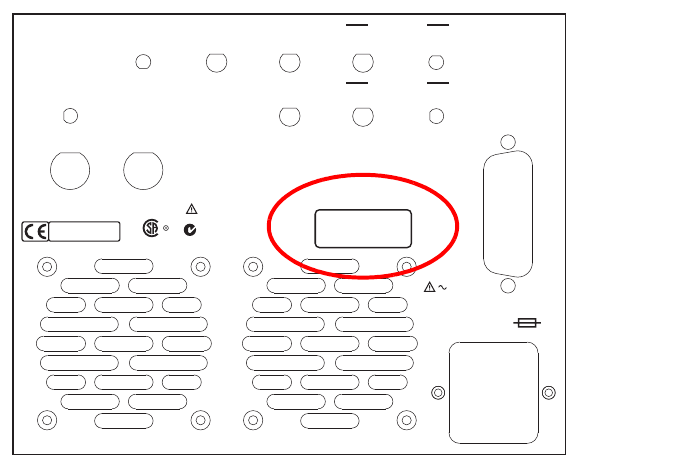
Determining your instrument’s serial number
When Agilent Technologies manufactures an instrument, it is given a unique
serial number. This serial number appears on a label on the rear panel of the
instrument (see Figure 340). The serial number has two parts. The first part
makes up the prefix and consists of four digits and a letter. The second part
makes up the suffix and consists of the last five digits on the label. The serial
number prefix is the same for all identical instruments; it changes only if the
electrical or physical functionality differs between instruments. However, the
serial number suffix changes sequentially from instrument to instrument to
uniquely identify every one.
Figure 340 Serial number location
GPIB
OUT
MULTIPLEXER
IN
SPECTRUM
ANALYZER
TUNE SPAN
OUT
IF
LEVEL
10 MHz OVEN
OUT
10 MHz IN
+
8 dBm -2 dBm
BUFFERED
10 MHz OUT
+
20 dBm
600 MHz OUT
0dBm
LABEL
SERIAL NUMBER
154258
ICES/NMB-001
ISM GRP.1 CLASS A
N10149
FUSE: T 3.15 A 250 V
100 MHz OUT
115 V/3 A
230 V/2 A
50/60 Hz
LINE
SEE USERS MANUAL