
User`s guide


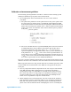

Table Of Contents
- Title Page
- Contents
- Getting Started
- Introduction and Measurement
- Phase Noise Basics
- Expanding Your Measurement Experience
- Starting the Measurement Software
- Using the Asset Manager
- Using the Server Hardware Connections to Specify the Source
- Setting GPIB Addresses
- Testing the 8663A Internal/External 10 MHz
- Testing the 8644B Internal/External 10 MHz
- Viewing Markers
- Omitting Spurs
- Displaying the Parameter Summary
- Exporting Measurement Results
- Absolute Measurement Fundamentals
- Absolute Measurement Examples
- Residual Measurement Fundamentals
- What is Residual Noise?
- Assumptions about Residual Phase Noise Measurements
- Calibrating the Measurement
- Measurement Difficulties
- Residual Measurement Examples
- FM Discriminator Fundamentals
- FM Discriminator Measurement Examples
- AM Noise Measurement Fundamentals
- AM Noise Measurement Examples
- Baseband Noise Measurement Examples
- Evaluating Your Measurement Results
- Advanced Software Features
- Reference Graphs and Tables
- Approximate System Noise Floor vs. R Port Signal Level
- Phase Noise Floor and Region of Validity
- Phase Noise Level of Various Agilent Sources
- Increase in Measured Noise as Ref Source Approaches DUT Noise
- Approximate Sensitivity of Delay Line Discriminator
- AM Calibration
- Voltage Controlled Source Tuning Requirements
- Tune Range of VCO for Center Voltage
- Peak Tuning Range Required by Noise Level
- Phase Lock Loop Bandwidth vs. Peak Tuning Range
- Noise Floor Limits Due to Peak Tuning Range
- Tuning Characteristics of Various VCO Source Options
- 8643A Frequency Limits
- 8644B Frequency Limits
- 8664A Frequency Limits
- 8665A Frequency Limits
- 8665B Frequency Limits
- System Specifications
- System Interconnections
- PC Components Installation
- Overview
- Step 1: Uninstall the current version of Agilent Technologies IO libraries
- Step 2: Uninstall all National Instruments products.
- Step 3: Install the National Instruments VXI software.
- Step 4: Install the National Instruments VISA runtime.
- Step 5: Install software for the NI Data Acquisition Software.
- Step 6: Hardware Installation
- Step 7. Finalize National Instruments Software Installation.
- Step 8: System Interconnections
- Step 9: Install Microsoft Visual C++ 2008 Redistributable Package use default settings
- Step 10: Install the Agilent I/O Libraries
- Step 11: Install the E5500 Phase Noise Measurement software.
- Step 12: Asset Configuration
- Step 13: License Key for the Phase Noise Test Set
- Overview
- PC Digitizer Performance Verification
- Preventive Maintenance
- Service, Support, and Safety Information
- Safety and Regulatory Information
- Safety summary
- Equipment Installation
- Environmental conditions
- Before applying power
- Ground the instrument or system
- Fuses and Circuit Breakers
- Maintenance
- Safety symbols and instrument markings
- Regulatory Compliance
- Declaration of Conformity
- Compliance with German noise requirements
- Compliance with Canadian EMC requirements
- Service and Support
- Return Procedure
- Safety and Regulatory Information
Residual Measurement Fundamentals
7
Agilent E5505A User’s Guide 209
Calibration and measurement guidelines
The following general guidelines should be considered when setting up and
making a residual two-port phase noise measurement.
1
For residual phase noise measurements, the source noise must be
correlated.
a
The phase delay difference in the paths between the power splitter and
the phase detector must be kept to a minimum when making residual
noise measurements. In other words, by keeping the cables between the
phase detector and power splitter short,
τ will be small. The attenuation
of the source noise is a function of the carrier offset frequency, and the
delay time
(τ) and is equal to:
b
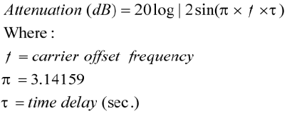
The source should also have a good broadband phase noise floor because
at sufficiently large carrier offsets it will tend to decorrelate when
measuring components with large delays. At , source noise is
rejected completely. the first null in noise can be used to determine the
delay difference. At , source noise shows up unattenuated. At
lower offsets, source noise is attenuated at 20 dB per decade rate at 0.1
of , source noise is attenuated 20 dB. Examples of sources which best
meet these requirements are the 8644B and 8642A/B.
The source used for making residual phase noise measurements must be low in
AM noise because source AM noise can cause AM to
ΦM conversion in the DUT.
Mixer-type phase detectors only provide about 20 to 30 dB of rejection to AM
noise in a
ΦM noise measurement so the AM noise can appear in the phase
noise plot
.
2
It is very important that all components in the test setup be well shielded
from RFI. Unwanted RF coupling between components will make a
measurement setup very vulnerable to external electric fields around it.
The result may well be a setup going out of quadrature simply by people
moving around in the test setup area and altering surrounding electric
fields. A loss of quadrature stops the measurement.
3
When making low-level measurements, the best results will be obtained
from uncluttered setups. Soft foam rubber is very useful for isolating the
DUT and other phase-sensitive components from mechanically-induced
phase noise. The mechanical shock of bumping the test set or kicking the
f
1
τ
---
=
f
1
2
π
τ
----------
=
1
2
π
τ
----------