
Technical data
Troubleshooting 4
6000 Series Oscilloscopes Service Guide 97
6 If all cables are properly connected and none of the
previous tests confirm a failure on another assembly,
replace the system board.
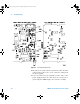
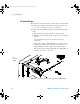
To check the 6000A Series display
1 Disconnect the power cord.
2 Check to verify that the backlight inverter cable is
connected.
3 Ensure the display LCD cable is connected.
4 Connect the power cord.
5 Use the DMM to check the Inverter Power voltage (see
table below).
6 If the voltage is incorrect, replace the system board.
7 If the voltage is correct, use an oscilloscope to check the
LCD clock (see table below).
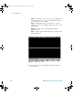
Table 15 Display Signals on the System Board
8 If the clock signal is good, replace the LCD.
9 If the clock signal is absent, replace the system board.
To check the 6000L Series display output
1 Connect a known good external XGA display and
power- up the display and the oscilloscope.
2 If the known good display does show an output from the
XGA port of the oscilloscope, replace the system board.
Signal Normal/Typical Result
Inverter Power J2750 Pin 3 or 4 5 V
Video Signal J2730 Pin 6 and 7 480 MHz clock
6000_series_service_guide.book Page 97 Friday, March 23, 2007 2:43 PM