
Technical data
96 6000 Series Oscilloscopes Service Guide
4 Troubleshooting
To check the 6000A Series or 6000L Series system board
1 Remove the cabinet.
2 Check that all cable connections are securely connected
from the system board to:
• Power supply
• Keyboard (6000A Series only)
• Display (6000A Series only)
• Inverter board (6000A Series only)
• Fan
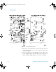
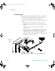
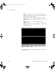
3 Verify the voltages at the system board test points listed
in the table below. Refer to Figure 14 on page 92 to
locate the test points.
Table 14 System Board Test Points
4 If the voltage at test point L3301 and/or L3302 is not
within the specified range, replace the system board.
5 (This step applies to 6000A Series models only)
If the voltage at test point L3204 and/or L3201 is not
correct:
• Disconnect J2730 from the system board and measure
pins 19 and 20 on the system board connector. This is
the voltage to the display, and it should be 3.3V. If it is
not, replace the system board. If the voltage is correct,
replace the display.
• Disconnect J2750 from the system board and measure
pins 3 and 4. This is the voltage to the inverter, and it
should be 5 V. If it is not, replace the system board. If
the voltage is correct, replace the display.
Test point Voltage Output from
regulator:
L3204 3.3 (+- 0.1) U3202
L3201 5.0 (+- 0.1) U3202
L3301 1.5 (+- 0.1) U3300
L3302 -5.2 (+- 0.1) U3301
6000_series_service_guide.book Page 96 Friday, March 23, 2007 2:43 PM