
Technical data

92 6000 Series Oscilloscopes Service Guide
4 Troubleshooting
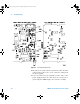
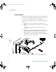
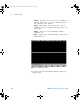
Figure 14 System Board Test Points
5 Disconnect the cable from the system board and check the
voltage between pins 9 & 5 of the connector coming from
the power supply.
6 If it is less than 14 V, the problem is in the cable or the
power supply. Remove the cable and test it for shorts or
opens using the DMM. Replace the defective assembly.
Pin 1
Pin 9
J3200
6000_series_service_guide.book Page 92 Friday, March 23, 2007 2:43 PM