
Technical data

88 6000 Series Oscilloscopes Service Guide
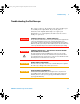
4 Troubleshooting
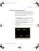
If you see the waveform, but the square wave is not
shaped correctly as shown above, perform the procedure
“To compensate the analog probes” on page 88.
If you do not see the waveform, ensure your power source
is adequate, the oscilloscope is properly powered- on, and
the probe is connected securely to the front- panel analog
channel input BNC and to the Probe Comp terminal.
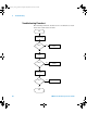
6 If you still do not see the waveform, use the
troubleshooting flowchart in this chapter to isolate the
problem.
To compensate the analog probes
You should compensate your analog probes to match their
characteristics to the oscilloscope’s channels. A poorly
compensated probe can introduce measurement errors.
1 Perform the procedure “To verify basic oscilloscope
operation” on page 87
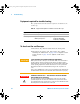
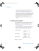
2 Use a nonmetallic tool to adjust the trimmer capacitor on
the probe for the flattest pulse possible. The trimmer
capacitor is located on the probe BNC connector.
Figure 13 Example pulses
comp.cd
r
Perfectly compensated
Over compensated
Under compensated
6000_series_service_guide.book Page 88 Friday, March 23, 2007 2:43 PM