
Technical data
66 6000 Series Oscilloscopes Service Guide
2 Testing Performance
2 Set up the oscilloscope.
a Press the Save/Recall key, then press the Default Setup
softkey.
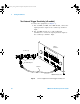
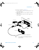
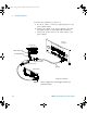
b On 300 MHz, 500 MHz, and 1 GHz models, set the
External Trigger impedance to 50 Ohm. 100 MHz models
do not have this option, so you need to use a 50 ohm
feedthrough terminator as shown in Figure 7.
c Change the trigger Mode from Auto to Normal.
d Use the Range softkey and the Entry knob to set the
range to 1.0 V.
3 Verify the trigger sensitivity at maximum frequency.
a Change the signal generator output frequency:
MSO/DSO6102A: 1 GHz
MSO/DSO6052A: 500 MHz
MSO/DSO6032A: 300 MHz
MSO/DSO6012A: 100 MHz
b Set the power meter Cal Factor % to the appropriate
value (100, 300, 500 MHz or 1 GHz) on the calibration
chart on the power sensor. If necessary, do a linear
interpolation if the correct factor is not included in the
power meter’s calibration chart.
c Adjust the signal generator output for a reading on the
power meter of 100µW. (200 mV
pp
= 70.71mV rms,
Power = Vin
2
/50Ω = 70.71 mV
2
/50Ω = 100µW.)
d Press the Trigger Edge key, then press the Source
softkey to set the trigger source to external trigger.
e Check for stable triggering and adjust the trigger level
if necessary. Triggering is indicated by the Trig’d
indicator at the top of the display. When it is flashing,
the oscilloscope is not triggered. When it is not
flashing, the oscilloscope is triggered.
f Record the results as Pass or Fail in the Performance
Test Record (see page 70).
If the test fails, see the "Troubleshooting" chapter. Then
return here.
6000_series_service_guide.book Page 66 Friday, March 23, 2007 2:43 PM