
Technical data

Testing Performance 2
6000 Series Oscilloscopes Service Guide 65
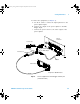
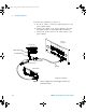
1 Connect the equipment (see Figure 7).
a Use the N cable to connect the signal generator to the
power splitter input.
b Connect one output of the power splitter to the Ext
Trigger input.
c Connect the power sensor to the other output of the
power splitter.
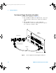
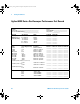
Figure 7 Connect equipment for external trigger sensitivity test
(2-channel models)
Oscilloscope
Signal
Generator
Power Meter
Power Splitter
Power Sensor
N to BNC adapter
N Cable
50Ω Feedthrough*
* Required for 100 MHz models.
6000_series_service_guide.book Page 65 Friday, March 23, 2007 2:43 PM