
Technical data
60 6000 Series Oscilloscopes Service Guide
2 Testing Performance
If the measurements are not within the test limits, go to
the “Troubleshooting” chapter. Then return here.
5 Change the calibrator to 100 ns markers. Change the time
base to 20 ns/div. Adjust the trigger level to obtain a
stable display.
6 Measure the following. If the measurements are not within
the test limits, go to the “Troubleshooting” chapter. Then
return here.
Period 100 ns— The test limits are 99.8 ns to 100.2 ns.
7 Change the time base and calibrator markers as follows:
a On 300 MHz, 500 MHz, and 1 GHz models, change time
base to 2 ns/div and the calibrator to 5 ns markers
b On 100 MHz models, change time base to 5 ns/div and
the calibrator to 10 ns markers
8 Make the following measurements. If the measurements
are not within the test limits, go to the “Troubleshooting”
chapter. Then return here.
a For 300 MHz, 500 MHz, and 1 GHz models, period 5 ns
— the test limits are 4.96 ns to 5.04 ns.
b For 100 MHz models, period 10 ns — the test limits are
9.93 ns to 10.07 ns.
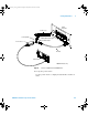
To verify trigger sensitivity
This test verifies the trigger sensitivity. In this test, you will
apply a sine wave to the oscilloscope at the upper
bandwidth limit. You will then decrease the amplitude of the
signal to the specified levels, and check to see if the
oscilloscope is still triggered.
The internal trigger sensitivity test is mandatory because it
is a specification. The external trigger test is optional
because it is a characteristic, not a specification.
6000_series_service_guide.book Page 60 Friday, March 23, 2007 2:43 PM