
Technical data

Testing Performance 2
6000 Series Oscilloscopes Service Guide 59
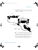
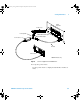
1 Connect the equipment:
a For 300 MHz, 500 MHz, and 1 GHz oscilloscope models,
connect the calibrator output to the oscilloscope
channel 1 input.
b For 100 MHz oscilloscopes, use a 50Ω feedthrough
termination to connect the calibrator output to the
oscilloscope channel 1 input.
2 Set up the signal source.
1 Select Marker on the oscilloscope calibrator.
2 Set the calibrator for 100 µs markers (period = 100 µs).
3 Set up the oscilloscope.
a Set channel 1 Coupling to DC.
b On 1 GHz, 500 MHz and 300 MHz models only, set
channel 1 Imped to 50 Ohm.
c Press the Display key, then set the Vectors softkey to off.
d Press the AutoScale key.
e Set the time base to 20 µs/div.
f Press the Main/Delayed key, then set the Time Ref softkey
to Left.
g Adjust the Trigger Level knob to obtain a stable
display.
4 Press the Quick Meas softkey, set the Source softkey to 1,
then press Select and choose Period. Press the Measure
softkey and measure the following:
Period 100 µs — The test limits are 99.8 µs to 100.2 µs.
Table 11 Equipment Required to Verify Horizontal ∆t Accuracy
Equipment Critical Specifications Recommended
Model/Part
Oscilloscope
Calibrator
Stability 5 ppm after 1/2 hour Fluke 5820A
Cable BNC, 3 feet Agilent 10503A
Feedthrough 50
Ω BNC (f) to BNC (m) Agilent 0960-0301
6000_series_service_guide.book Page 59 Friday, March 23, 2007 2:43 PM