
Technical data

Testing Performance 2
6000 Series Oscilloscopes Service Guide 57
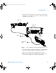
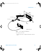
9 Change the signal generator output frequency according to
the maximum frequency for the oscilloscope using the
following:
• 1 GHz Models: 1 GHz
• 500 MHz Models: 500 MHz
• 300 MHz Models: 300 MHz
• 100 MHz Models: 100 MHz
10 Referencing the frequency from step 9, set the power
meter Cal Factor % to the frequency value on the
calibration chart on the power sensor.
11 Set the oscilloscope sweep speed according to the
following:
• 1 GHz Models: 500 ps/div
• 500 MHz Models: 1 ns/div
• 300 MHz Models: 2 ns/div
• 100 MHz Models: 5 ns/div
12 Note the oscilloscope Std Dev(1) reading at the bottom of
the screen.
13 Note the reading on the power meter and covert to Vrms
using the expression:
14 Calculate the response using the expression:
Example If:
Pmeas
1_MHz
= 892 uW
Std Dev(n)
1MHz
= 210.4 mV
Pmeas
max_freq
= 687 uW
Std Dev(n)
max freq
= 161.6 mV
V
in
max_freq
Ω×= 50
max freq
Pmeas
response(dB) = 20 log
10
MHz 1 MHz1
freqmax freqmax
Vin / Vout
Vin / Vout
6000_series_service_guide.book Page 57 Friday, March 23, 2007 2:43 PM