
Technical data

54 6000 Series Oscilloscopes Service Guide
2 Testing Performance
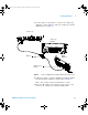
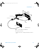
1 Connect the equipment (see Figure 5).
a Use the N cable to connect the signal generator to the
input of the power splitter input.
b Connect the power sensor to one output of the power
splitter.
c For 300 MHz, 500 MHz, and 1 GHz oscilloscope models
use an N-to- BNC adapter to connect the other splitter
output to the channel 1 input.
d For 100 MHz oscilloscopes, use an N- to- BNC adapter
and 50Ω feedthrough termination to connect the other
splitter output to the channel 1 input on the
oscilloscope.
Table 10 Equipment Required to Verify Bandwidth
Equipment Critical Specifications
Recommended
Model/Part
Signal Generator 100 kHz - 1 GHz at 200 mVrms Agilent E4400B/8648A
Power Meter/Sensor 1 MHz - 1 GHz ±3% accuracy Agilent E4418B/8482A
Power Splitter outputs differ by < 0.15 dB Agilent 11667A
Cable Type N (m) 24 inch Agilent 11500B
Adapter Type N (m) to BNC (m) Agilent 1250-0082
Feedthrough 50Ω BNC (f) to BNC (m) Agilent 0960-0301
6000_series_service_guide.book Page 54 Friday, March 23, 2007 2:43 PM