
Technical data

Testing Performance 2
6000 Series Oscilloscopes Service Guide 41
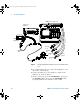
To construct the test connector (for use with MSO models only)
Agilent 6000 Series Oscilloscopes that have digital channels
enabled require the test connector described below. Follow
the steps to build the test connector.
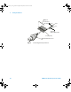
1 Obtain a BNC connector and an 8-by-2 section of Berg
strip.
2 On one side of the Berg strip, solder a jumper wire to all
of the pins (shown in Figure 1 on page 42).
3 On the other side of the Berg strip, solder another jumper
wire to all of the pins.
4 Solder the center of the BNC connector to a center pin on
one of the rows on the Berg strip.
5 Solder the ground tab of the BNC connector to a center
pin on the other row on the Berg strip.
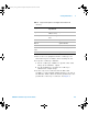
Table 5 Materials required to construct the test connectors
Description Recommended Part Qty
BNC (f) Connector Agilent 1250-1032 or
Pomona 4578
1
Berg Strip, 8-by-2 1
Jumper wire
6000_series_service_guide.book Page 41 Friday, March 23, 2007 2:43 PM