
Technical data

Replacing 6000L Assemblies 6
6000 Series Oscilloscopes Service Guide 149
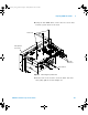
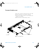
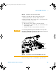
Figure 51 Preparing to remove the system board
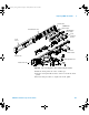
6 Using a 9/23-inch hex driver, remove the two hex
standoffs and washers from the GPIB connector
7 Using a T10 Torx driver, remove the 5 screws that hold
the system board to the deck.
8 Remove the system board
a Lift the back of the board to clear the chassis.
b Gently pull the board out until you can disconnect the
power supply cable.
c Continue to remove the board from the chassis.
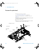
9 Reverse this procedure to reinstall the system board:
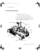
CAUTION
To avoid tearing the thermal pads on a 500 MHz oscilloscope when
removing or installing the system board, hold the board up, away from
the thermal pads until all components are clear.
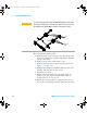
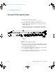
Figure 52 Avoid damage to thermal pads (500 MHZ models only)
ICs
Thermal
Pads
6000_series_service_guide.book Page 149 Friday, March 23, 2007 2:43 PM