
Technical data

148 6000 Series Oscilloscopes Service Guide
6 Replacing 6000L Assemblies
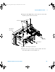
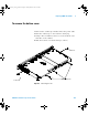
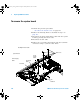
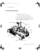
To remove the system board
1 Perform the previous procedures:
• “To remove the bottom cover” on page 145
2 Remove the intensity knob as described in step 2 on
page 146.
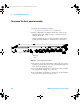
3 Disconnect the front panel ribbon cable from the system
board by pressing the release tabs.
4 Disconnect the fan cable.
5 Remove the 3 hex nuts and washers from the rear BNC
connectors using a 5/8- inch socket driver.
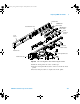
T10 Screws
Fan Cable
System Board
Backlight Inverter Cable
Power Supply
Cable
Front Panel
Cable
Power
Supply
Cable
Hex
Standoffs
6000_series_service_guide.book Page 148 Friday, March 23, 2007 2:43 PM