
Technical data

143
Agilent Technologies
Agilent 6000 Series Oscilloscopes
Service Guide
6
Replacing 6000L Assemblies
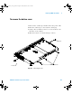
To remove the bottom cover 145
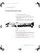
To remove the front panel assembly 146
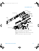
To remove the system board 148
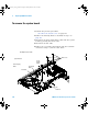
To remove the power supply 150
To remove the fan 152
To remove the AC power input assembly 154
To remove the power shaft 156
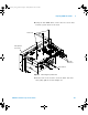
This chapter describes how to remove assemblies from the
Agilent 6000L Series Oscilloscopes. After you have removed
an assembly, to install the replacement assembly, follow the
instructions in reverse order.
The parts shown in the following figures are representative
and may look different than what you have in your
oscilloscope.
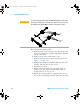
Tools Used for Disassembly
Use these tools to remove and replace the oscilloscope
assemblies:
• T10 TORX drivers
• 5/8- inch and 9/32- inch socket drivers
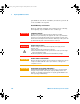
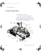
See how the Oscilloscope Parts Fit Together
An exploded view of the oscilloscope is included in the
Chapter 8, “Replaceable Parts for the Agilent 6000L
Oscilloscope,” starting on page 163. It shows the individual
6000_series_service_guide.book Page 143 Friday, March 23, 2007 2:43 PM