
Technical data

142 6000 Series Oscilloscopes Service Guide
5 Replacing 6000A Assemblies
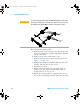
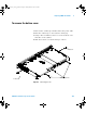
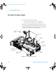
12 To reinstall the system board:
a Insert the tabs on the board into the slots in the front
of the sheet metal; the intensity shaft, BNCs, and CAL
lug into their holes.
b Push the back of the board down to seat.
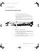
c Reinstall the T6 screws on the front panel (shown in
Figure 20 on page 107).
d Reinstall the GP-IB hex standoffs, BNC hex nuts and
washers, and then the five T10 screws.
e Reconnect the cables.
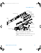
f Ensure that the backlight, fan, and LCD cables are
routed to the left of the keyboard ribbon cable as
shown in Figure 46 on page 140.
g Replace the intensity knob by supporting the back of
the encoder and pushing the knob fully onto the shaft.
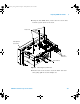
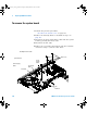
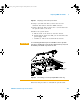
CAUTION
To avoid tearing the thermal pads (on MSO/DSO601xA models) when
removing or installing the system board, hold the board up, away from
the thermal pads until the BNCs and other components are clear.
ICs
Thermal
pads
6000_series_service_guide.book Page 142 Friday, March 23, 2007 2:43 PM