
Technical data

140 6000 Series Oscilloscopes Service Guide
5 Replacing 6000A Assemblies
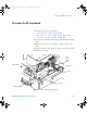
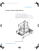
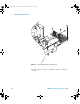
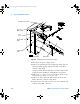
Figure 46 Preparing to remove the system board
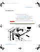
5 Disconnect the power supply cable.
6 Remove the intensity knob by grasping the knob with one
hand and gently prying using a flat- blade screwdriver
with the other hand.
Using a twisting motion with the screwdriver rather than
prying prevents marking or damaging the front panel.
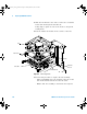
7 Remove the 3 or 4 T6 screws located by the BNCs on the
front panel (see Figure 20 on page 107).
8 Remove the three hex nuts and washers from the rear
BNCs using the 5/8- inch socket driver.
9 Using the 9/32 hex driver, remove two hex standoffs and
washers from GPIB connector.
Main Shield
Display (LCD)
Cable
System Board
Backlight Inverter Cable
Power Supply
Cable
Fan
Cable
Keyboard
Ribbon Cable
6000_series_service_guide.book Page 140 Friday, March 23, 2007 2:43 PM