
Technical data

101
Agilent Technologies
Agilent 6000 Series Oscilloscopes
Service Guide
5
Replacing 6000A Assemblies
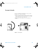
To remove the cabinet 104
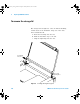
To remove the handle 105
To remove the storage lid 106
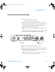
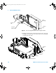
To remove the front panel assembly 107
To remove the keyboard assembly 110
To remove the display assembly 113
To remove the display assembly 113
To remove the backlight inverter board and e-field shield 117
To remove the LCD, gasket, and protective lens from the display
mount 122
To remove the power supply shield 125
To remove the power supply 129
To remove the power shaft 130
To remove the AC input board 131
To remove the batteries (Option BAT only) 133
To remove the battery controller board (Option BAT only) 135
To remove the fan 137
To remove the system board 139
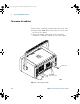
This chapter describes how to remove assemblies from the
Agilent 6000A Series Oscilloscopes. After you have removed
an assembly, to install the replacement assembly, follow the
instructions in reverse order.
The parts shown in the following figures are representative
and may look different than what you have in your
oscilloscope.
6000_series_service_guide.book Page 101 Friday, March 23, 2007 2:43 PM